Section 9: Control Box Connections
Assembly Note - Motor Direction
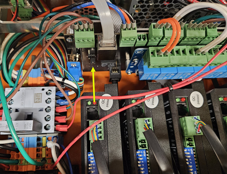
Prior to connecting your EX controller to your Benchtop PRO Machine, you will need to ensure a jumper on your interconnect card is correctly set so that the Y axis motors turn in the same direction.
- Locate the jumper on the card near the middle of your controller, as shown in the first image.
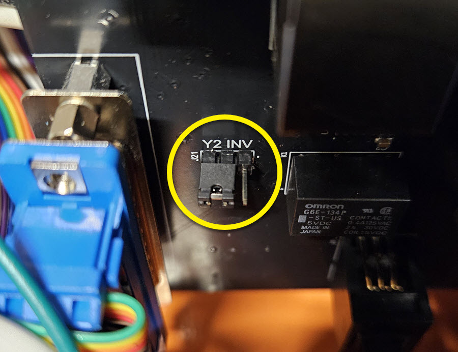
- Verify that the jumper in is the position shown, covering the two pins nearest the "J21" label.
Parts List
| QTY | Part/Description | Packaged In |
|---|---|---|
| 1 | EX Controller | EX Controller Kit |
| (1) Emergency Stop Cable, 20' | ||
| (1) Emergency Stop Switch | ||
| (1) C13 Power Cable | ||
| (1) Ethernet Cable, 10' | ||
| (1) M12 Sensor Cable, 12' | ||
| 1 | M12 Splitter | Electronics Proximity Sensor Kit |
9.1 NEMA 23 Electronics
Section Note
Skip to Section 9.2 if you are using a NEMA 34 electronics package.
9.1.1
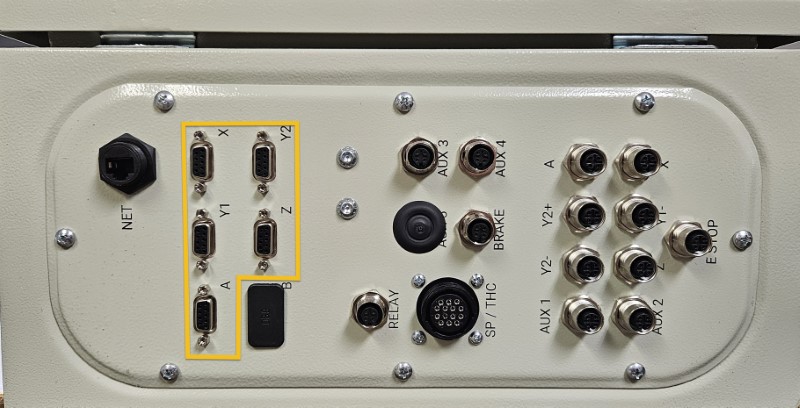
- Connect each motor cable to the appropriate motor port.
Assembly Note
The A motor port is used for either a CNC Rotary Axis, or the U axis (second Z axis) on a dual-use machine.
9.1.2
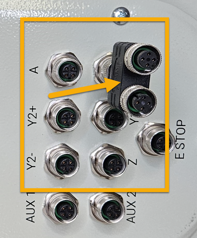
- Install the M12 splitter in the port labeled "X" on your controller.
9.1.3
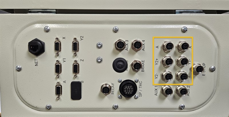
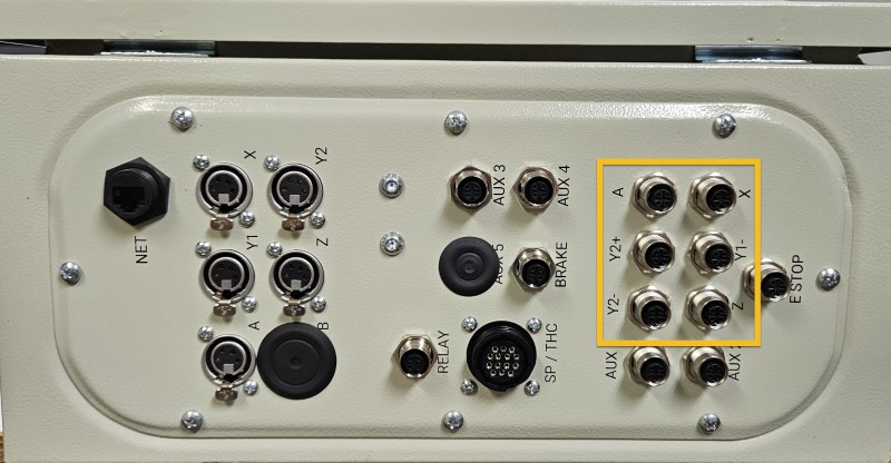
- Connect each sensor cable to the appropriate sensor port.
- The X- and X+ sensor cables will plug into the splitter installed in the previous step.
9.1.4
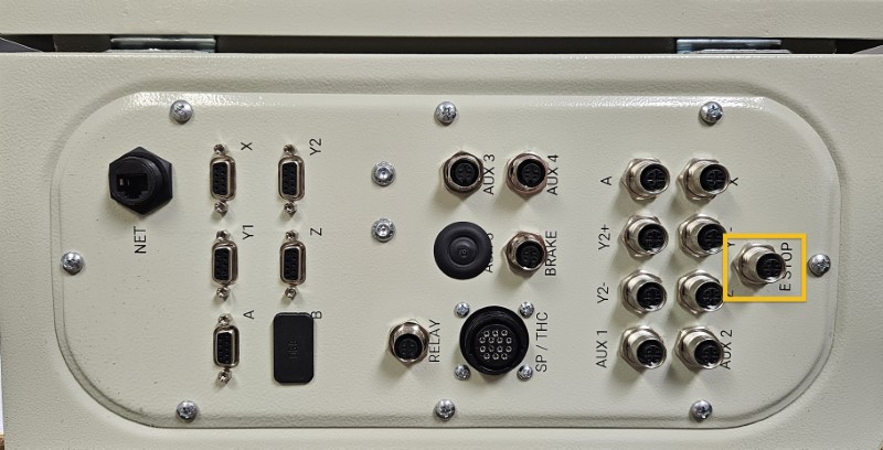
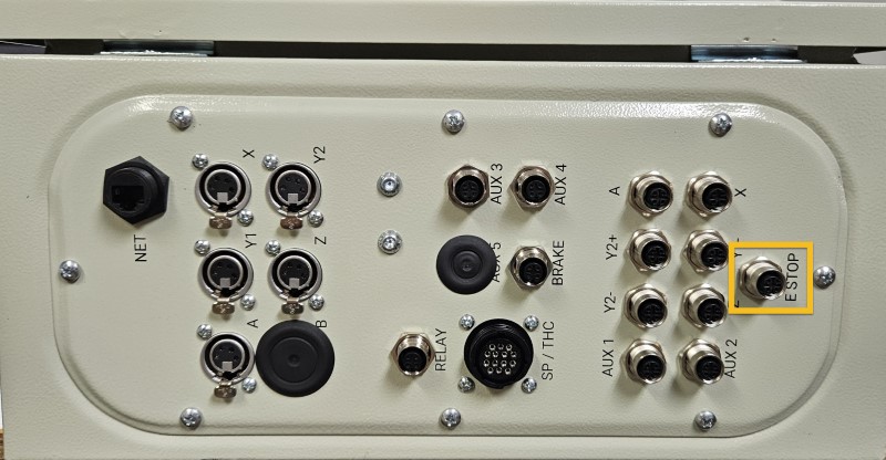
- Connect the Emergency Stop Cable, 20' to the E Stop port.
- Connect the other end of this cable to the Emergency Stop Switch .
9.1.5 - Spindle / Router Applications
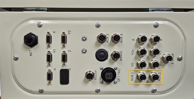
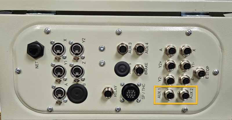
- Connect the Tool Height Setter to the Aux 2 port.
- Connect the optional Auto Z and Corner Finding Touch Plate to the Aux 1 port.
9.1.6 - Plasma Applications
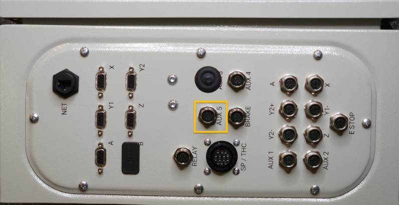
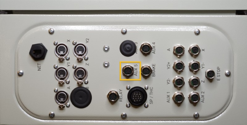
- Connect the Torch Mount sensor cable directly to the Aux 5 port.
9.1.7 - Spindle / Plasma Applications
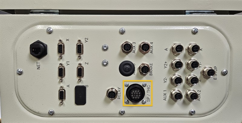
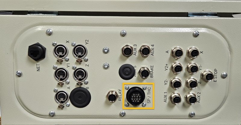
- Connect the existing SP/THC Cable to the SP/THC port.
- Depending on your current cutting method, this cable will be connected to either the Plug and Play Spindle / VFD Control Box, or your Hypertherm plasma power unit.
9.1.8
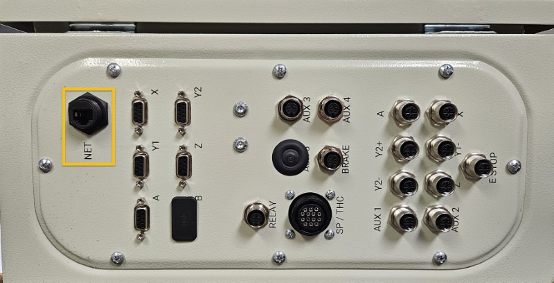
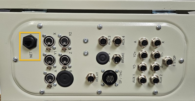
- Connect the Ethernet Cable, 10' to the NET port.
- Connect the other end of the Ethernet cable to your control PC.
Ethernet Cable
Please ensure you're using the Ethernet cable included with the kit. The provided cable is shielded to reduce unwanted signal interference.
9.1.9
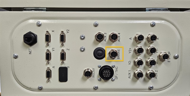
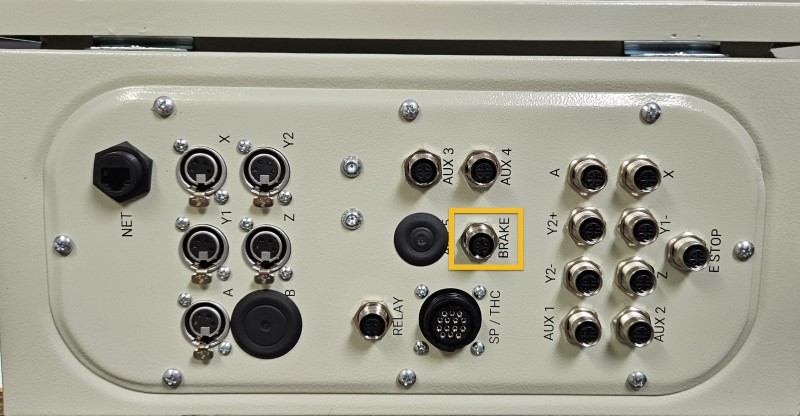
- Connect the Z-axis brake cable to the Brake port.
9.2 NEMA 34 Electronics
9.2.1
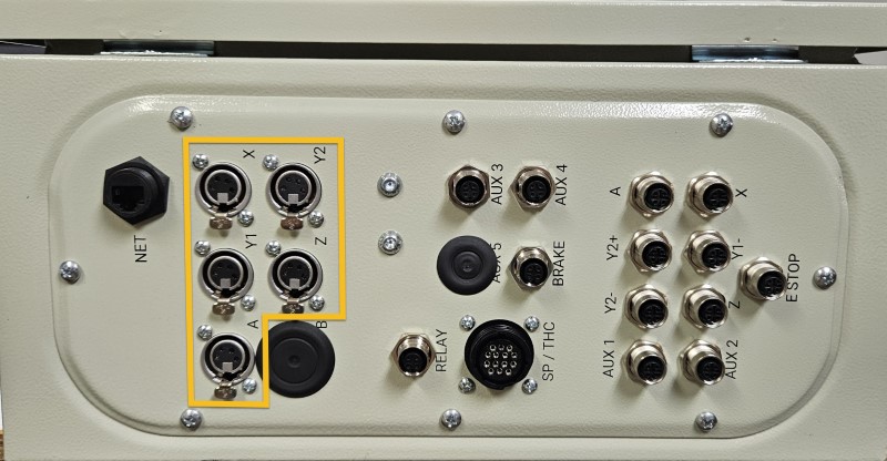
- Connect each motor cable to the appropriate motor port.
Assembly Note
The A motor port is used for either a CNC Rotary Axis, or the U axis (second Z axis) on a dual-use machine.
9.2.2
- Install the M12 splitter in the port labeled "X" on your controller.
9.2.3
- Connect each sensor cable to the appropriate sensor port.
- The X- and X+ sensor cables will plug into the splitter installed in the previous step.
9.2.4
- Connect the Emergency Stop Cable, 20' to the E Stop port.
- Connect the other end of this cable to the Emergency Stop Switch .
9.2.5 - Spindle / Router Applications
- Connect the Tool Height Setter to the Aux 2 port.
- Connect the optional Auto Z and Corner Finding Touch Plate to the Aux 1 port.
9.2.6 - Plasma Applications
- Connect the Torch Mount sensor cable directly to the Aux 5 port.
9.2.7 - Spindle / Plasma Applications
- Connect the existing SP/THC Cable to the SP/THC port.
- Depending on your current cutting method, this cable will be connected to either the Plug and Play Spindle / VFD Control Box, or your Hypertherm plasma power unit.
9.2.8
- Connect the Ethernet Cable, 10' to the NET port.
- Connect the other end of the Ethernet cable to your control PC.
Ethernet Cable
Please ensure you're using the Ethernet cable included with the kit. The provided cable is shielded to reduce unwanted signal interference.
9.2.9
- Connect the Z-axis brake cable to the Brake port.