Laser Upgrade
Before Beginning
- Drive the gantry to a position where the Laser Deploy is within easy reach.
- Power down and unplug the system from wall power. Open the Laser Controller enclosure.
1. Retrofit Laser Controller
Parts List
| ID | QTY | Part/Description | Packaged In |
|---|---|---|---|
A | 1 | Laser Control Module, 45W | CRP5110-00-XT8-UP |
B | 1 | 24V Power Supply, 350W | CRP5110-00-XT8-UP |
C | 2 | Power Supply Hang Bracket | CRP5110-00-XT8-UP |
D | 2 | Screw, M4x6 (SHC) | CRP5110-00-XT8-UP |
E | 1 | Cable Gland with XLR Cable Whip | CRP5110-00-XT8-UP |
F | 1 | Laser Control Module Wire Harness | CRP5110-00-XT8-UP |
G | 1 | Power Supply Wire Harness | CRP5110-00-XT8-UP |
Tools List
| Requirement | Tool |
|---|---|
| Required | Phillips Screwdriver |
| Required | Small Flathead Screwdriver |
| Required | T10 Torx Screwdriver |
| Required | 3mm Allen Wrench |
| Required | 2.5mm Allen Wrench |
1.1
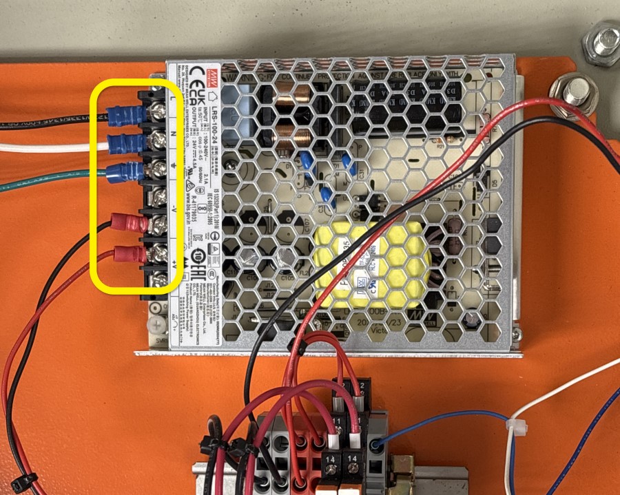
- Loosen all screw terminals and remove the fork connectors from the existing LRS-100-24 Power Supply.
1.2
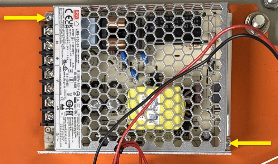
- Unmount the power supply by removing the T10 Torx screws.
- Remove the power supply from the enclosure.
1.3
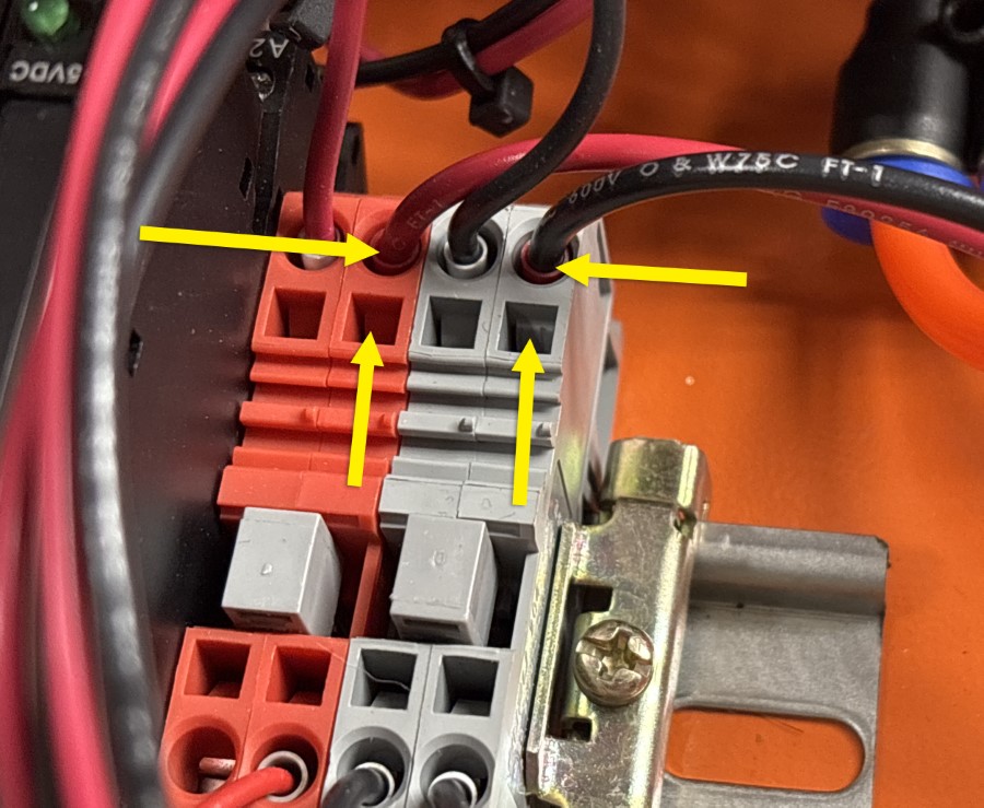
- Locate the Red and Black wires that connected to the removed power supply.
- Remove both wires from the terminal blocks.
- To remove: insert a screwdriver into the square opening next to the wire. Push the top of the screwdriver away from the wire position to open the terminal and remove the wire.
1.4
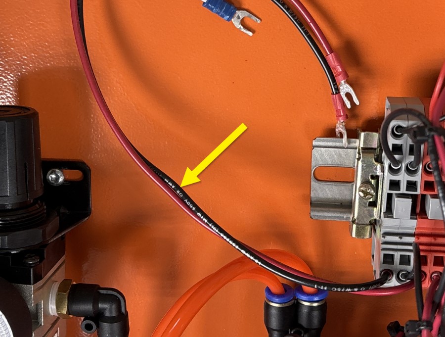
- Replace the wires removed from the terminal blocks with the included Power Supply Wire Harness G.
- Using the same method as removal, insert the ferruled ends into the respective ports.
- Insert the Black wire into the Gray terminal block.
- Insert the Red wire into the Red terminal block.
1.5
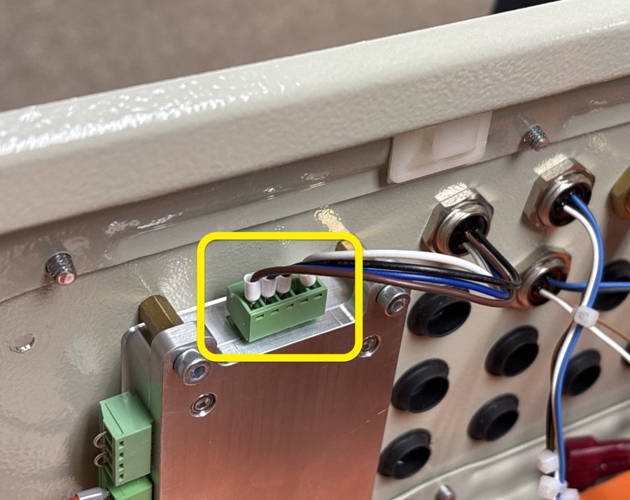
- Remove the indicated 5-pin terminal block from the Laser Control Module.
1.6
- Loosen the screw terminals on the terminal block and remove the wires.
- Save the terminal block for a later step.
1.7
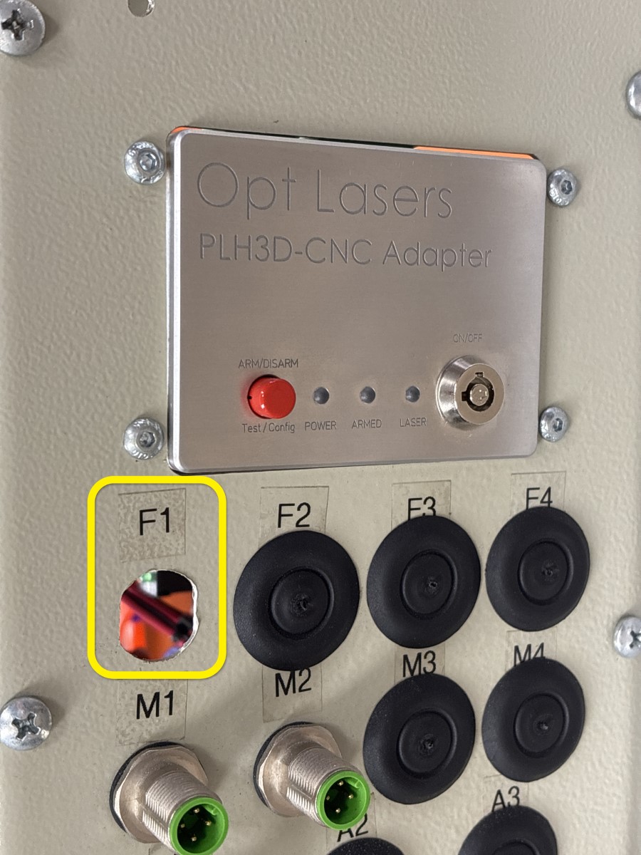
- Remove the M12 panel mount connector labeled F1. This is the same wire harness removed from the control module in the previous step. The M12 panel mount connector is not reused.
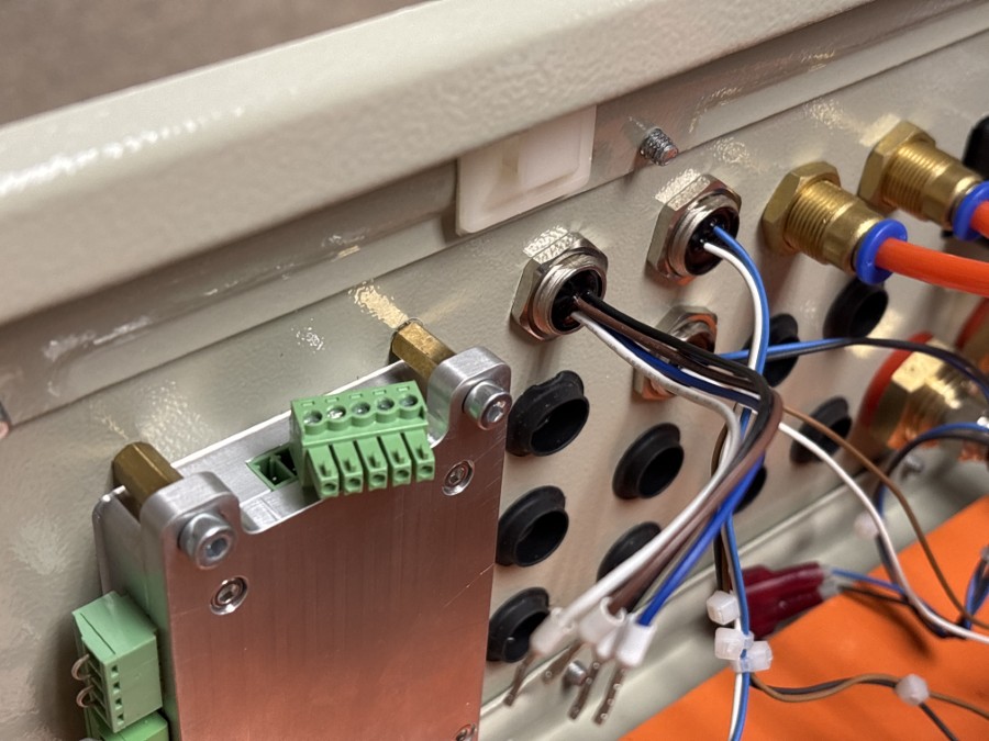
1.8
- Disconnect the 6-pin green terminal block from the Laser Control Module.
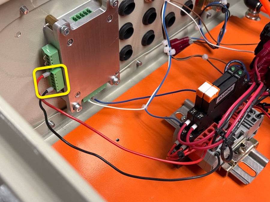
1.9
- Loosen the screw terminals retaining the Black wire and Red wire and remove them from the green terminal block.
- Save the 6-pin green terminal block for a later step.
1.10

- Remove the disconnected Black and Red wires from the Red and Gray terminal blocks.
- Replace with the new Laser Control Module Wire Harness F. The new harness uses thicker gauge wires and ferrules.
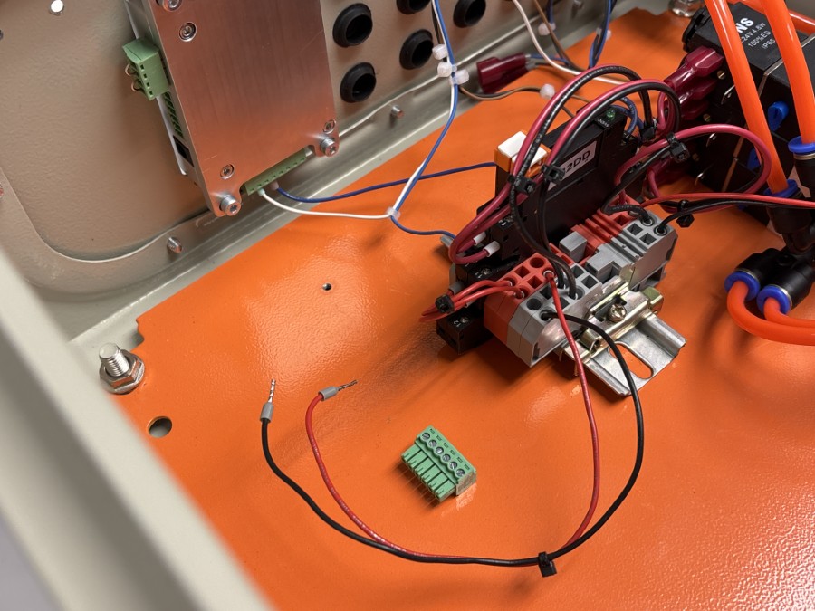
1.11

- Connect the 5-pin green terminal block removed in a previous step to the newly installed Red and Black wires in the orientation and positions shown.
1.12

- Remove and save the remaining 8-pin green terminal block from the Laser Control Module. Do not disconnect the individual wires.
- Unmount the Laser Control Module from inside the Laser Controller enclosure by removing the four screws. Save the screws for a later step.
1.13

- Loosen and remove the lock nut of the Cable Gland with XLR Cable Whip E and insert the cable into the F1 port on the Gland Plate.
1.14

- Secure the Cable Gland with XLR Cable Whip E by reinstalling the lock nut from the back of the Gland Plate. Do not fully tighten the lock nut at this time.
1.15

- Locate the 6-pin green terminal block previously removed from the old Laser Control Module.
- Connect the four wires from the Cable Gland with XLR Cable Whip E to the terminal block as shown.
1.16

- Install the previously removed 8-pin green terminal block into the new Laser Control Module A.
1.17

- Mount the new Laser Control Module A to the gland plate standoffs with the four saved mounting screws.
1.18

- Connect the 5-pin and 6-pin green terminal blocks to the Laser Control Module A as shown.
- Determine an appropriate length for this XLR Cable Whip which avoids putting strain on the green terminal block connections. Excess length outside the enclosure is not necessary. Tighten the lock nut to set the length.
1.19

- Use the switch on the side of the 24V Power Supply, 350W B to select the desired input voltage range (either 115VAC or 230VAC) to match your AC power.
1.20

- Fasten the Power Supply Hang Brackets C to the top edge of the 24V Power Supply B with Screws, M4x6 D.
- Position the Brackets with the gap towards the back face of the Power Supply (see image detail).
1.21

- Hook the Brackets over the top edge of the Laser Controller enclosure Orange Plate.
1.22

- Connect the incoming AC power wires and Black / Red Power Supply Wire Harness G to the terminals on the new 24V Power Supply as shown in the table.
| Wire Color | Origin | Power Supply Terminal |
|---|---|---|
| Red | Terminal Block | +V |
| Black | Terminal Block | -V |
| Green | Enclosure Stud | ⏚ (Earth / Ground) |
| White | AC Power | N |
| Black | AC Power | L |
2. Retrofit Laser Deploy
Parts List
| ID | QTY | Part/Description | Packaged In |
|---|---|---|---|
A | 1 | Opt XT8 Laser Head, 45W | CRP5130-00-01-04 |
B | 1 | Moving Lift Spring Bracket | CRP5120-00-XT8-UP |
C | 1 | Static Lift Spring Bracket | CRP5120-00-XT8-UP |
D | 1 | Universal Adapter Plate | CRP5120-00-XT8-UP |
E | 1 | Hose, 4mm | Use existing |
F | 2 | Screw, M8x20 (BHC) | CRP5120-00-XT8-UP |
G | 2 | Screw, M4x10 (SHC) | CRP5120-00-XT8-UP |
H | 10 | Screw, M3x10 (SHC) | CRP5120-00-XT8-UP |
I | 8 | Screw, M3x8 (PH) | CRP5120-00-XT8-UP |
J | 1 | Lift Spring | CRP5120-00-XT8-UP |
K | 1 | Laser Control XLR Cable, 28' | CRP5120-00-XT8-UP |
L | 1 | Nozzle Cap | CRP5120-00-XT8-UP |
M | 1 | Thread Locker Adhesive | CRP5120-00-XT8-UP |
Tools List
| Requirement | Tool |
|---|---|
| Required | Phillips Screwdriver |
| Required | Metric Allen Wrenches 2.5mm, 3mm, 5mm, 6mm |
2.1

- Hold the Deploy in the extended position using a spacer (piece of wood shown).
2.2

- Disconnect the Hose, 4mm E from the existing 6mm x 4mm adapter.
2.3

- Remove the 8 screws and unmount the 15W laser head from the Moving Plate.
- Disconnect the Hose, 4mm E from the 15W laser head and set aside for reuse.
2.4

-
Unpack the Laser Head A and install the protective Nozzle Cap L.
Assembly Note
Avid CNC recommends that the Nozzle Cap L be installed on the nozzle whenever the Laser is not in use to keep the Laser components free of dust and debris.
2.5

- Route the Hose, 4mm E through the body of the Laser Head A.
- Push the hose through the hole until it exits at the bottom of the Laser Head. You may need to rotate and wiggle the hose at some points.
2.6

- Connect the Hose, 4mm E to the push-to-connect fitting at the laser nozzle.
- Rotate the fitting so it sits recessed in the shroud.
2.7

- On the side of the Moving Plate opposite your spindle body or cutting tool, install the Moving Lift Spring Bracket B by replacing the existing Socket Head Cap Screw with a M8x20 Screw F.
- Replace the other Socket Head Cap Screw with the second M8x20 Screw F.
2.8

- On the backside of the existing Actuator Plate, install the Static Lift Spring Bracket C with M4x10 Screws G.
- Ensure the Static Lift Spring Bracket is installed on the same side as the Moving Lift Spring Bracket as the two will be connected by a spring in a later step.
2.9

- Attach the Universal Adapter Plate D to the Laser Head A using M3x10 Screws H. Use the lowest holes on the Laser Head, as illustrated, for most applications.
- Ensure the countersunk holes on the Universal Adapter Plate are facing away from the Laser Head.
2.10

- Remove the screws holding the small backplate at the top of the Laser Head to reveal a pluggable block.
- Connect the Laser Control XLR Cable K here. Once connected, replace the backplate.
2.11

- Attach the Laser Head A assembly to the Moving Plate using seven M3x8 Screws I at the indicated locations. Use the supplied Thread Locker Adhesive M on the M3x8 Screws I and tighten until snug. Secure the top right screw first through the smaller hole on the Moving Plate to properly align the parts.
Assembly Note
The upgrade kit includes eight M3x8 Screws I - only seven are used during this upgrade.
2.12

- Carefully remove the spacer holding the Deploy in the extended position and allow the assembly to retract.
- Loop the Lift Spring J over the Static and Moving Spring Brackets.
3. Software Setup
Legacy CRP800/Mach4 Systems
- Please see Mach4 Laser Users Guide to calibrate X/Y offsets for the new laser head.
EX Control/CNC12 Systems
Power on the EX Controller and Laser Controller enclosures. Open Centroid CNC Control software.

- From the Home Screen, enter the Utility Menu (F7) and then the Acorn Wizard (F10).

-
Navigate to Accessories then Laser. Change Laser Type to "XT8 Laser".
- If your version of Avid CNC Centroid does not have the "XT8 Laser" option:
- An update for CNC12 may be available at CNC12 for Avid CNC Machines.
- Optionally, you may change Laser Type to "Custom" and:
- set Custom Nozzle Size to "Yes"
- set Z Offset to 0.335 (equal to 8.5mm)
- If you have manually adjusted the nozzle distance on your XT8 laser head, your Z Offset value may be different. You may use the included 21mm block between the laser body and a solid surface, then measure the nozzle distance.

- If your version of Avid CNC Centroid does not have the "XT8 Laser" option:
-
When you are ready to save the changes you've made to the profile, click the "Write Settings" button to continue. Follow the on-screen prompts to save and apply your settings.
- Follow these steps for calibrating your laser offsets in CNC12:
Video: Avid CNC Laser setup & use on EX Control - https://youtu.be/-hA91cyZlIc