AV Smart Spindle Retrofit Guide
Assembly Note
Ensure both your CNC control box and your Spindle control box are powered off with the power cables unplugged.
Before You Begin
- This document will assist you with replacing your cutting tool with the Avid CNC AV70S or AV40S Spindle/VFD Kit.
- Some steps may be skipped based on your current system configuration.
- Throughout the instructions, you will see notes similar to the examples shown below:
Alternate Install Option
Alternate Install notes include information for installation of components in alternate configurations. You may click on the heading to expand a collapsed note.
Section Note
Section Notes contain information that is specific to an entire section of instructions.
1. Spindle Controller
Section Note
This section applies if you are replacing your Spindle Controller. If your new spindle is compatible with your existing spindle controller, please skip to Section 2. The AV70S is compatible with Avid CNC 8.7HP spindle controllers and the AV40S is compatible with Avid CNC 3HP and 4HP spindle controllers.
Parts List
| ID | QTY | Part/Description | Packaged In |
|---|---|---|---|
1 | Key and Panel Hardware Bag | Spindle Controller Kit | |
A | 3 | M8 x 20mm Hex Bolt | Key and Panel Hardware Bag |
B | 3 | M8 Hex Nut | Key and Panel Hardware Bag |
C | 3 | Mounting Bracket | Key and Panel Hardware Bag |
D | 3 | M8 x 25mm Set Screw | Reused Hardware* |
E | 3 | M8 Hex Flange Nut | Reused Hardware* |
F | 3 | M8 Roll-in T-nut | Reused Hardware* |
* For new installs, this hardware will be included with the Spindle Controller Kit. | |||
Tools List
| Requirement | Tool |
|---|---|
| Required | Adjustable Wrench |
| Recommended | 13mm Combination Wrench |
1.1 - Remove Existing Spindle Controller
Note
This step applies only if you are replacing an existing Avid CNC spindle controller as part of your upgrade. If your existing spindle controller is not being replaced, please skip to Section 2. If you do not have an existing Avid CNC spindle controller, please skip to Step 1.2.
- Disconnect the M23 cable and 14-pin SP/THC cable from the bottom of the existing spindle controller.
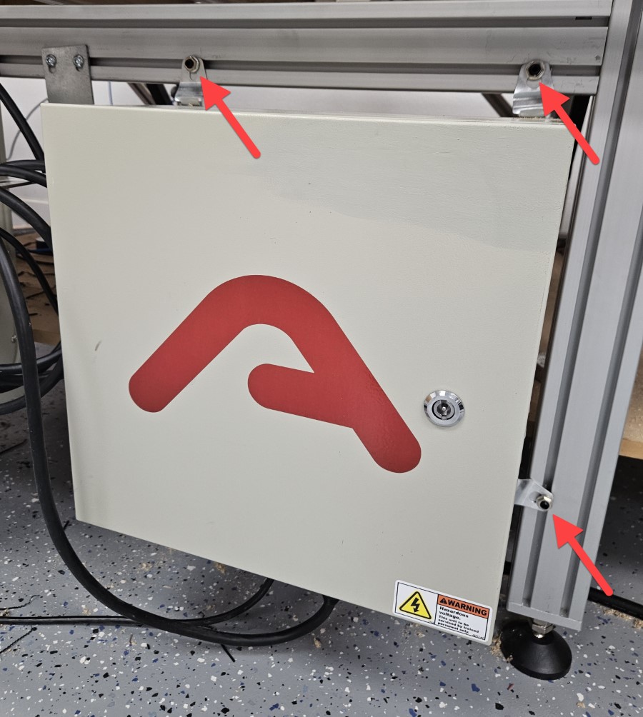
- Remove the spindle controller from the machine by removing the M8 Hex Flange Nuts E at the indicated locations. Keep the flange nuts for installation of the new controller.
1.2 - Install New Spindle Controller
1.2.1

- At the indicated locations, remove the plastic plugs from the new Plug and Play Spindle/VFD Control Box.
Alternate Cable Track Location
If your cable track is on the left side of the machine, remove the plug from the bottom right instead of the bottom left.
1.2.2

- At the locations with removed plugs, attach a Mounting Bracket C using M8 x 20mm Hex Bolts A and M8 Hex Nuts B .
1.2.3

- If you're installing a replacement VFD control box, install new unit with the M8 Hex Flange Nuts removed in a previous step. Otherwise, see #2.
- Attach the VFD control box to the leg kit using M8 x 25mm Set Screws D , M8 Hex Flange Nuts E , and M8 Roll-in T-Nuts F .
Alternate Cable Track Location
If your cable track is on the left side of the machine, attach the VFD control box to the left side of the machine.
2. Spindle Motor
Parts List
| ID | QTY | Part/Description | Packaged In |
|---|---|---|---|
A | 6 | M8 x 20mm Socket Head Cap Screw | Mounting Fasteners |
B | 1 | M8 x 30mm Hex Cap Screw | Mounting Fasteners |
C | 4 | M6 x 20mm Socket Head Cap Screw | Mounting Fasteners |
D | 1 | M8 Shoulder Bolt | Reused Hardware* |
E | 1 | M8 x 30mm Socket Head Cap Screw | Reused Hardware* |
F | 1 | M8 x 35mm Socket Head Cap Screw | Reused Hardware* |
G | 1 | Eccentric Bushing | Reused Hardware* |
H | 1 | Spindle | Spindle |
* For new installs, this hardware will be included with the Spindle Tramming Kit. | |||
Tools List
| Requirement | Tool |
|---|---|
| Required | 5mm Allen Wrench |
| Required | 6mm Allen Wrench |
| Required | Adjustable Wrench |
| Recommended | 13mm Combination or Ratcheting Wrench |
| Recommended | Torque Wrench (up to 15 ft-lb / 20 Nm) |
| Recommended | 5mm Hex Bit for Torque Wrench used with CRP144-33 Base Adapter |
| Recommended | 6mm Hex Bit for Torque Wrench used with CRP144-23 Base Adapter |
2.1 - Remove Existing Spindle
2.1.1
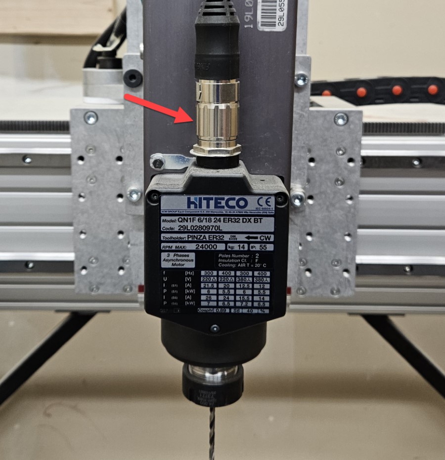
- Disconnect the M23 cable from the existing spindle. If you have a router mount, unplug your router and remove it from the mount.
2.1.2
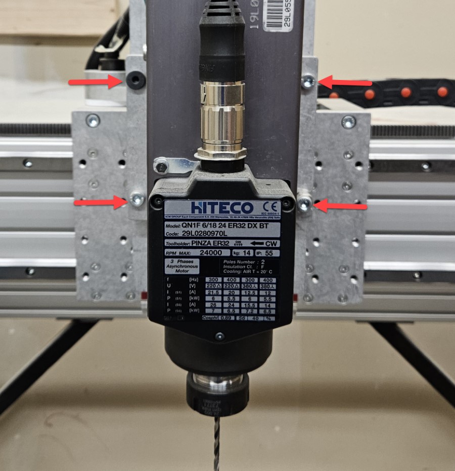
- Remove the existing spindle or router mount from the machine by removing the screws connecting the base adapter to the tramming plate. Save hardware for installation of the new spindle.
2.1.3
-
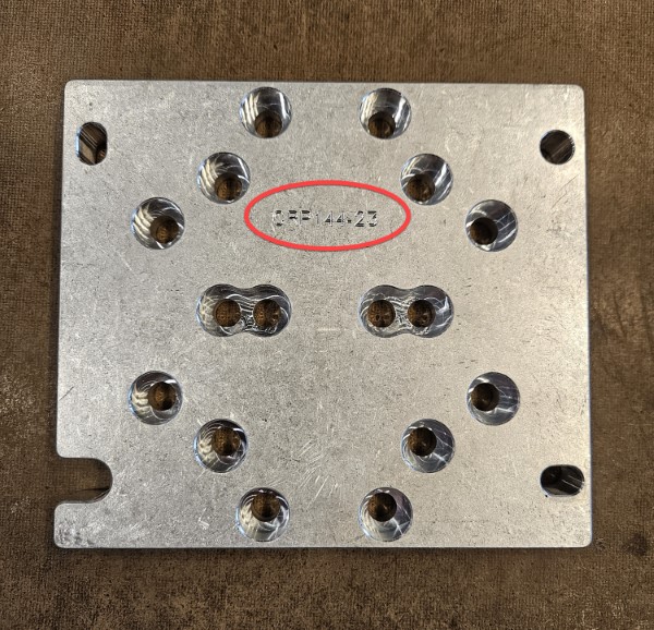
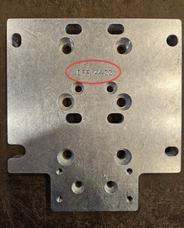
If you have a spindle, remove the base adapter from the spindle. If you have a router mount, remove the mount from the base adapter.
- Depending on your spindle/router configuration, your Base Adapter will be either CRP144-23 or CRP144-33. The part number is engraved on the Base Adapter, as shown.
2.2 - Install Spindle
2.2.1

- Insert the M8 x 30mm Hex Cap Screw B into the hole on the Base Adapter as shown prior to installing Base Adapter on the spindle. The location is identical for all Base Adapter models. This screw will be used in a later step.
- If you are reusing fasteners that were previously removed, this Hex Cap Screw is a replacement for the original fastener at the indicated location.
2.2.2

- Install the base adapter on the back of the Spindle H, using the provided:
- six M8 x 20mm Socket Head Cap Screws A for Base Adapter CRP144-23
- Tighten the M8 fasteners to 13-15 ft-lb (17-20 Nm).
- four M6 x 20mm Socket Head Cap Screws C for Base Adapter CRP144-33
- Tighten the M6 fasteners to 62-70 in-lb (5-6 ft-lb, 7-8 Nm).
- six M8 x 20mm Socket Head Cap Screws A for Base Adapter CRP144-23
Assembly Note
Do not overtighten the fasteners or you may cause damage to the spindle body.
2.2.3


- Install the Base Adapter (attached to the spindle) onto the tramming plate using an M8 Shoulder Bolt D, M8 x 30mm Socket Head Cap Screw E, M8 x 30 mm Hex Cap Screw previously inserted through base adapter, and M8 x 35mm Socket Head Cap Screw F, and Eccentric Bushing G. With the exception of the Hex Cap Screw, this hardware is reused from when you removed the spindle from the machine.
Assembly Note
The spindle is hidden for illustrative purposes.
2.2.4

- Fully tighten the fasteners.
Assembly Note
The spindle is hidden for illustrative purposes.
3. Air Hose and Spindle Cabling
Parts List
| ID | QTY | Part/Description | Packaged In |
|---|---|---|---|
1 | Spindle Air Preparation Kit | ||
A | 1 | Assembled Air Regulator | Spindle Air Preparation Kit |
B | 2 | M6 x 12mm Socket Head Cap Screw | Spindle Air Preparation Kit |
C | 2 | M6 Roll-in T-nut | Spindle Air Preparation Kit |
D | 1 | 6mm Hose | Spindle Air Preparation Kit |
E | 1 | 8mm Hose | Spindle Air Preparation Kit |
F | 1 | 8mm to 6mm Wye Fitting | Spindle Air Preparation Kit |
G | 1 | 8-pin M23 Cable* | Spindle Controller Kit |
1 | Power Adapter and Cable Kit | ||
H | 1 | 8-pin M12 Cable, 28' | Power Adapter and Cable Kit |
I | 1 | 24V Wall Adapter | Power Adapter and Cable Kit |
* Included when installing or replacing VFD Control Box only. | |||
Tools List
| Requirement | Tool |
|---|---|
| Required | 5mm Allen Wrench |
| Required | Standard (Flat Tip) Screwdriver |
| Required | Wire Snips, Scissors or Utility Knife (for cutting hose) |
3.1 - Install Air Regulator

- Install the Air Regulator A on the inside front face of the electronics bar using M6 x 12mm Socket Head Cap Screws B and M6 Roll-in T-nuts C.
Assembly Note
The air regulator mounting location shown is the default location. The regulator may be located elsewhere for covenience.
3.2 - Prepare Spindle Air Connection

- Cut the 6mm Hose D (shorter segment) into two equal lengths.
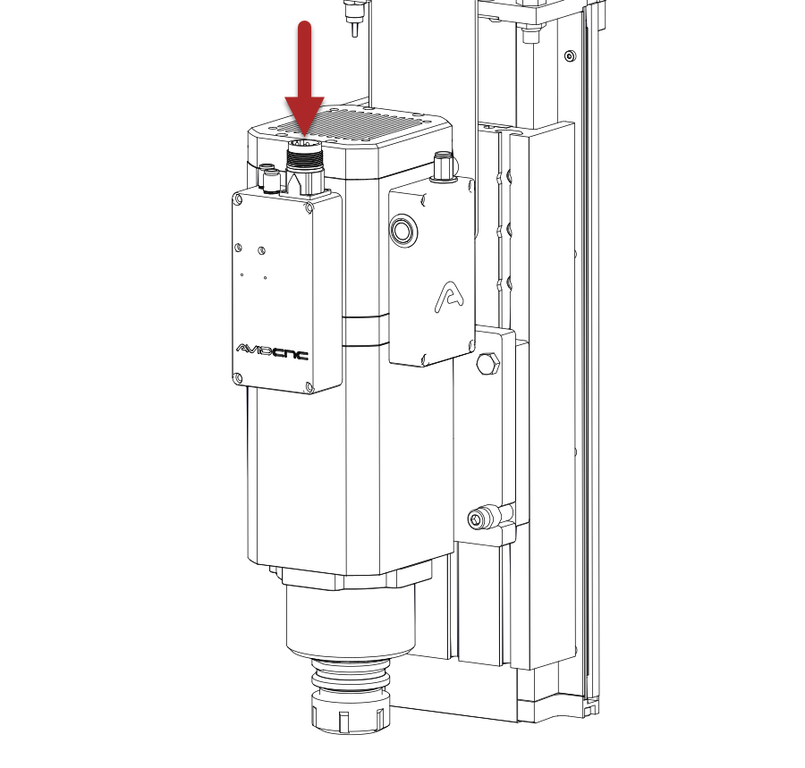
- Insert the two pieces of 6mm Hose D into the fittings on the top of the box located at the front of the spindle motor.
- Insert the free ends of the hose segments into the 8mm to 6mm Wye Fitting F.
Assembly Note
The final spindle air connection will be made during cable routing through the cable track in a later step.
3.3 - Air Hose and Cable Routing
3.3.1

- Prior to routing cables through the cable track, it is recommended to open each cable track link using a small screwdriver.
3.3.2
Note
This step applies to upgrades where the spindle controller is being replaced along with the spindle. If you are not replacing your spindle controller, you will keep your existing M23 cable.

| Connection | Color | Cable/Hose | Routing Path |
|---|---|---|---|
| Spindle | BLUE | M23 Cable | Through Z axis cable track, gantry cable track, and table cable track |
- For systems where an existing spindle controller is being replaced, remove the existing M23 cable from the machine.
- Route the new M23 Cable G as indicated. The path is identical to the M23 cable you removed.
3.3.3

| Connection | Color | Cable/Hose | Routing Path |
|---|---|---|---|
| Spindle | RED | 8-pin M12 Cable | Through Z axis cable track, gantry cable track, and table cable track |
| Spindle | BLUE | 8mm Hose | Through Z axis cable track, gantry cable track, and table cable track |
- Route the 8-pin M12 Cable, 28' H and 8mm Hose E as indicated. The path is identical to the M23 cable routed in the previous step, if applicable.
- Connect one end of the 8mm Hose E to the 8mm to 6mm Wye Fitting at the spindle and the other end to the Air Regulator.
- Supply air to the Air Regulator and set the pressure to 105 PSI (functional range: 95-115 PSI).
- Connect one end of the 8-pin M12 Cable H to the corresponding panel mount on the spindle and the other end to the 24V Wall Adapter I.
3.3.4
- Connect your M23 cable to the spindle.
- Carefully check that the machine has full range of motion and there is no strain on your new connections.
3.3.5
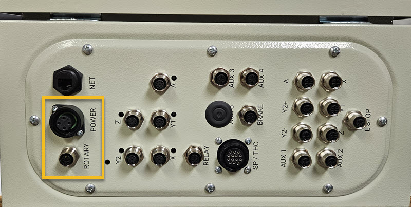
- Connect the M23 cable to the indicated port on the VFD Control Box.
3.3.6
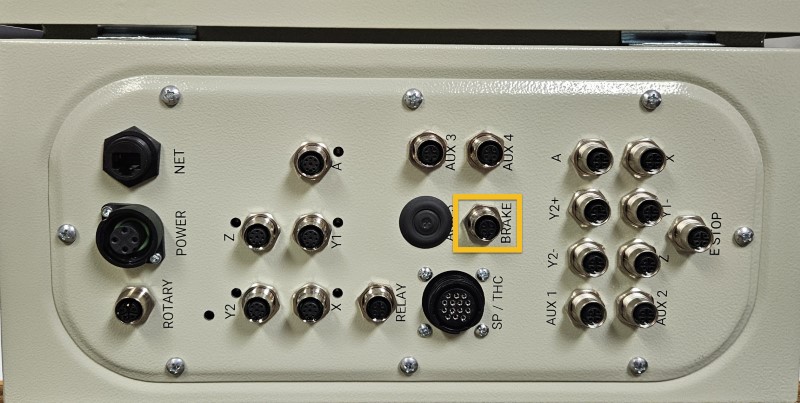
- Connect the 14-pin SP/THC cable to the indicated port on the VFD Control Box.
- Ensure the other end of the 14-pin SP/THC cable is connected to the CNC Control Box.
4. Tool Tightening Fixture
Parts List
| ID | QTY | Part/Description | Packaged In |
|---|---|---|---|
1 | ISO30 Tightening Fixture Kit | CRP5531-00-01 | |
A | 2 | M8 Roll-in T-nut | ISO30 Tightening Fixture Kit |
B | 2 | M8 x 25mm Socket Head Cap Screw | ISO30 Tightening Fixture Kit |
C | 1 | Tool Tightening Fixture Base Assembly | ISO30 Tightening Fixture Kit |
Tools List
| Requirement | Tool |
|---|---|
| Required | 6mm Allen Wrench |
4.1 - Install Tool Tightening Fixture

- Insert M8 Roll-in T-nuts A in the slot on the bottom of the front table crossmember, or other convenient location.
- Use M8 x 25mm Socket Head Cap Screws B to attach the Tool Tightening Fixture Base Assembly C to the machine frame.