AV Smart Spindle User Guide
Software Setup
CNC12
Note
We recommend updating to the latest Avid CNC profile version 5.24 or newer. You can find current profiles for CNC12 at CNC12 Software Downloads.
Configure CNC12 for AV70S
Select the appropriate Spindle Type in CNC12 Configuration Wizard
- CNC12 Profile v5.24 and newer: AV70S Smart Spindle
- CNC12 Profile v5.22 and older: 8.7 HP[1]
Configure CNC12 for AV40S
Select the 4 HP Spindle[2] in CNC12 Configuration Wizard
Mach4
Configure Mach4 for AV70S
- To configure Mach4 for use with the Avid CNC AV70S, use the Avid CNC Mach4 Configuration menu to set Spindle Type to 8.7HP Avid spindle[1].
Configure Mach4 for AV40S
- To configure Mach4 for use with the Avid CNC AV40S, use the Avid CNC Mach4 Configuration menu to set Spindle Type to 4HP Avid spindle[2].
[1] The Avid CNC AV70S and 8.7HP spindles have the same RPM operating range. If AV70S support is not included in your CNC control software, choosing the 8.7HP spindle will allow the AV70S to perform within its recommended performance envelope (min/max RPM). Additional features of the AV Smart Spindles, like automated tool change routines, are not available at this time without additional scripts.
[2] The Avid CNC AV40S and 4HP spindles have the same RPM operating range. If AV40S support is not included in your CNC control software, choosing the 4HP spindle will allow the AV40S to perform within its recommended performance envelope (min/max RPM). Additional features of the AV Smart Spindles, like automated tool change routines, are not available at this time without additional scripts.
Spindle Interface
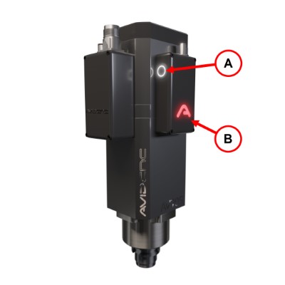
MTC Button (A)
Operation: Press and hold the button to open (un-clamp) the drawbar.
LED States:
- ON: The spindle is stopped and tool changes are allowed.
- OFF: Tool changes are not allowed. The spindle may be moving, or tool changes may be inhibited via the M12 connector.
Avid Logo LED (B)
When the Avid logo is lit, the AV spindle's microcontroller is properly powered.
Tool Holder
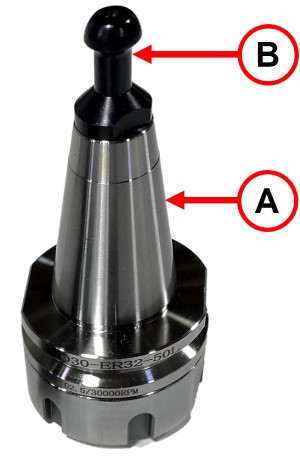
Taper (A)
The ISO30 taper locks into the spindle to transmit cutting forces.
Pull Stud (B)
The HSD style pull stud is pulled by the spindle's drawbar to lock the tool holder in place.
Manual Tool Change
Insert A Tool Holder
Safety Note
When the drawbar engages the toolholder, it pulls the tool holder up ~0.1" with a very high force. Make sure this motion will not pinch or cut your hand.
- Check that the spindle is stopped and the MTC button is illuminated.
- Before inserting a tool holder, make sure the taper and pull stud are free of debris.
- Press and hold the MTC button.
- Insert the tool holder until it stops.
- Release the MTC button to capture the tool.
Remove A Tool Holder
Safety Note
Pressing the MTC button with a tool holder in the spindle will cause it to immediately drop the tool. Make sure to support the tool before pressing the button.
- Check that the spindle is stopped and the MTC button is illuminated.
- Support the tool holder with one hand.
- Press and hold the MTC button.
- Remove the tool holder.
- Release the MTC button.