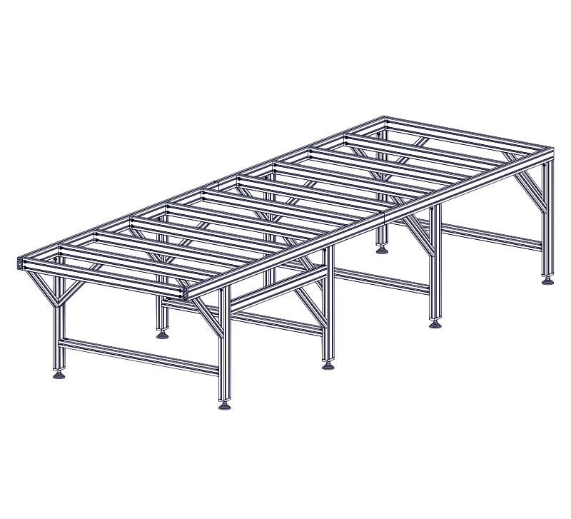
1. Base Frame
Section Note
Images may not be representative of actual machine size, however assembly steps and parts lists are specific for the machine configuration selected.
1.1 - Table Leg Assembly
Section Note
It is important to keep the leg kit extrusion separated from the table frame extrusion during unboxing. Only leg kit extrusion is used in this section.
Parts List
| ID | QTY | Part/Description | Package Label |
|---|---|---|---|
A | 4080 Leg Crossmember Extrusion, 650mm (25-9/16") 4080 Leg Crossmember Extrusion, 950mm (37-3/8") 4080 Leg Crossmember Extrusion, 1250mm (49-1/4") 4080 Leg Crossmember Extrusion, 1550mm (61") 4080 Leg Crossmember Extrusion, 1850mm (72-13/16") 4080 Leg Crossmember Extrusion, 2200mm (86-5/8") 4080 Leg Crossmember Extrusion, 2500mm (98-7/16") | Leg Extrusion | |
B | 4080 Leg Extrusion, 750mm (29-1/2") | Leg Extrusion | |
C | 1 | 4080 Electronics Bar Extrusion, 790mm (31-1/8") 4080 Electronics Bar Extrusion, 1090mm (42-15/16") 4080 Electronics Bar Extrusion, 1440mm (56-11/16") 4080 Electronics Bar Extrusion, 1080mm (42-1/2") | Leg Extrusion |
Leg Assembly Hardware CRP813-00-LEGSET-HW-BAG-21.1 | Base Hardware | ||
D | 40 Series Anchor Fastener (12 per bag) | CRP813-00-LEGSET-HW-BAG-21.1Packaged in | |
E | M8 x 30mm Socket Head Cap Screw (12 per bag) | CRP813-00-LEGSET-HW-BAG-21.1Packaged in | |
F | M8 x 16mm Socket Head Cap Screw (4 per bag) | CRP813-00-LEGSET-HW-BAG-21.1Packaged in | |
G | M8 Roll-in T-Nut (12 per bag) | CRP813-00-LEGSET-HW-BAG-21.1Packaged in | |
H | Foot Plate (2 per bag) 7111 | CRP813-00-LEGSET-HW-BAG-21.1Packaged in | |
I | Leveling Foot (2 per bag) H172 | CRP813-00-LEGSET-HW-BAG-21.1Packaged in | |
1 | Electronics Bar Hardware CRP813-00-ELCBAR-HW-BAG | Base Hardware | |
J | 4 | 40 Series Anchor Fastener | CRP813-00-ELCBAR-HW-BAGPackaged in |
K | 4 | M8 x 30mm Socket Head Cap Screw | CRP813-00-ELCBAR-HW-BAGPackaged in |
L | 4 | M8 Roll-in T-Nut | CRP813-00-ELCBAR-HW-BAGPackaged in |
1 | PRO Splice Kit CRP810-00-SP-21.1 | Base Hardware | |
M | 2 | Splice Bar CRP810-02 | CRP810-00-SP-21.1Packaged in |
| Remaining parts from CRP813-00-LEGSET-HW-BAG-21.1 used in future section | |||
| Remaining parts from CRP813-00-ELCBAR-HW-BAG used in future section | |||
| Remaining parts from CRP810-00-SP-21.1 used in future section | |||
Tools List
| Requirement | Tool |
|---|---|
| Required | 6mm Ball-End Allen Wrench |
| Required | Adjustable Wrench |
| Required | Tape Measure |
| Recommended | 6mm Hex Ball-End Power Bit |
1.1.1 - Anchor Fastener Installation
1.1.1.1
- Thread M8 x 30mm Socket Head Cap Screws E into the M8 Roll-in T-Nuts G through 40 Series Anchor Fasteners D .
1.1.1.2
- Slide the anchor assemblies into a piece of 4080 Leg Crossmember Extrusion, 950mm (37-3/8") 4080 Leg Crossmember Extrusion, 1250mm (49-1/4") 4080 Leg Crossmember Extrusion, 1550mm (61") 4080 Leg Crossmember Extrusion, 1850mm (72-13/16") 4080 Leg Crossmember Extrusion, 2200mm (86-5/8") 4080 Leg Crossmember Extrusion, 2500mm (98-7/16") A .
Assembly Note
It can be helpful to use a small piece of masking tape to hold the anchor assemblies in the extrusion during leg assembly.
1.1.1.3
- Repeat the previous steps to install anchor fasteners on both sides of all 4080 Leg Crossmember Extrusion, 950mm (37-3/8") 4080 Leg Crossmember Extrusion, 1250mm (49-1/4") 4080 Leg Crossmember Extrusion, 1550mm (61") 4080 Leg Crossmember Extrusion, 1850mm (72-13/16") 4080 Leg Crossmember Extrusion, 2200mm (86-5/8") 4080 Leg Crossmember Extrusion, 2500mm (98-7/16") A .
Assembly Note
It can be helpful to use a small piece of masking tape to hold the anchor assemblies in the extrusion during leg assembly.
1.1.2 - Leveling Feet Installation
1.1.2.1
- Attach the Foot Plate H to a piece of 4080 Leg Extrusion, 750mm (29-1/2") B using M8 x 16mm Socket Head Cap Screws F .
Assembly Note
Attach the foot plate to the end of the extrusion that has tapped holes.
1.1.2.2
- Thread the M16 Hex Nut N onto the Leveling Foot I and attach to the foot plate installed in the previous step.
1.1.2.3
- Repeat this process for each of the 4080 Leg Extrusion, 750mm (29-1/2") B pieces.
Assembly Note
Initially thread the leveling feet all of the way into the foot plate. After machine assembly, final adjustments will be made in the table leveling procedure.
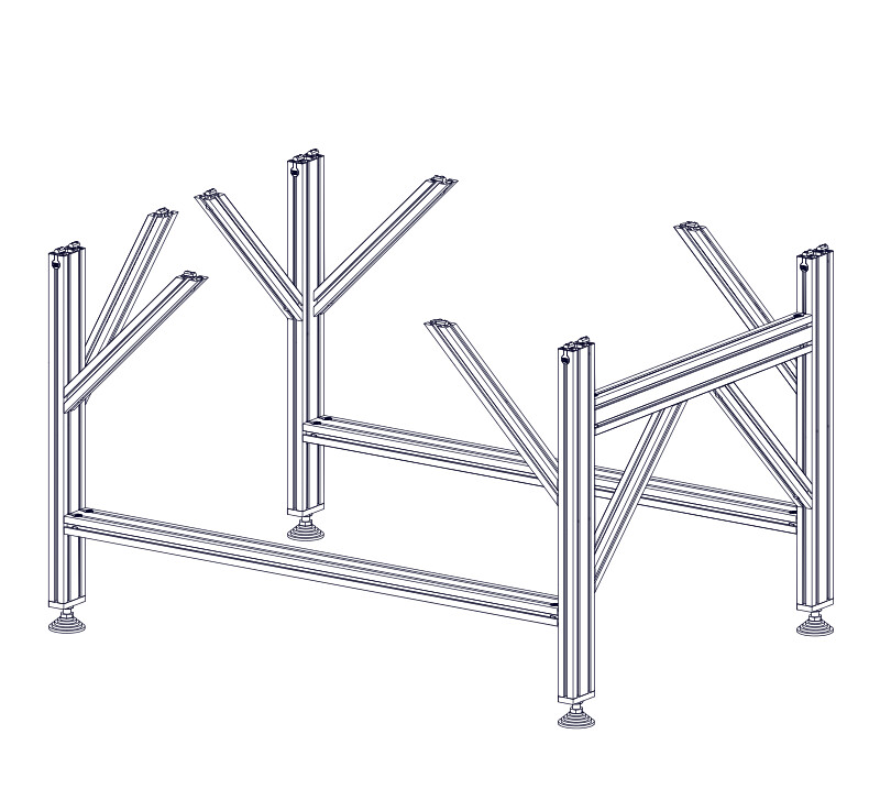
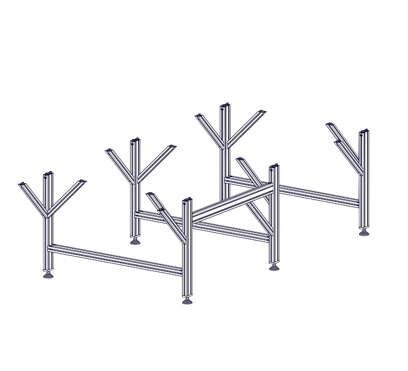
1.1.3 - Leg Crossmember Installation
1.1.3.1

- Use one of the previously assembled leg crossmembers to join two of the legs.
1.1.3.2

- Position the leg crossmember 165mm (6-1/2") from the bottom of the leg as indicated.
1.1.3.3

- On each side of the leg crossmember tighten the anchor fasteners, alternating between fasteners.
Assembly Note
For tightening the anchor fasteners, an M6 ball-end allen wrench is required. An M6 ball-end driver attachment for a drill or impact driver can make assembly more efficient.
1.1.3.4


- Repeat this process to assemble two three four five six seven eight nine 10 11 sets of legs.
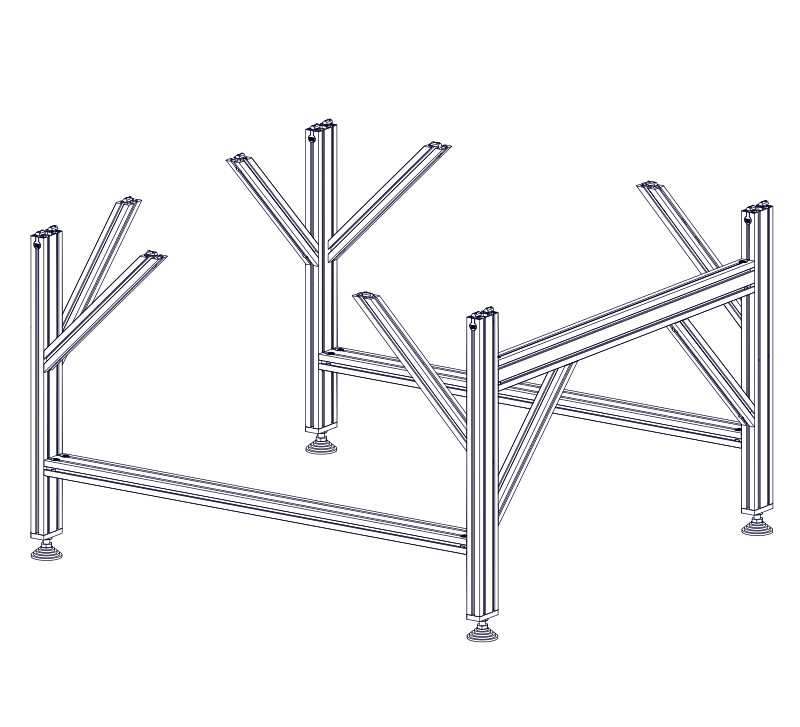
1.1.4 - Electronics Bar Installation
1.1.4.1
- Assemble four anchor fasteners (M8 x 30mm Socket Head Cap Screws K , 40 Series Anchor Fasteners J , and M8 Roll-in T-Nuts L ) and install in the 4080 Electronics Bar Extrusion, 790mm (31-1/8") 1090mm (42-15/16") 1440mm (56-11/16") 1080mm (42-1/2") 1080mm (42-1/2") 1080mm (42-1/2") 1080mm (42-1/2") 1080mm (42-1/2") C .
1.1.4.2

- Slide the electronics bar onto two of the leg assemblies.
Alternate Cable Track Location
If locating the table cable track on the left side of the machine, install the electronics bar on the opposite end of the two leg assemblies.
1.1.4.3

- Position the electronics bar 120mm (4-3/4") from the top of the leg extrusion.
- Fully tighten the indicated fasteners.
Assembly Note
Measure from the top of the leg extrusion at each end of the electronics bar.
1.1.4.4
- At the top of the indicated legs, partially thread M8 x 30mm Socket Head Cap Screws E into a Splice Bar M through 40 Series Anchor Fasteners D .
Assembly Note
Install splice bars only on ONE leg assembly. When installing the frame extrusion in later steps, the instructions will indicate when to use this leg assembly.
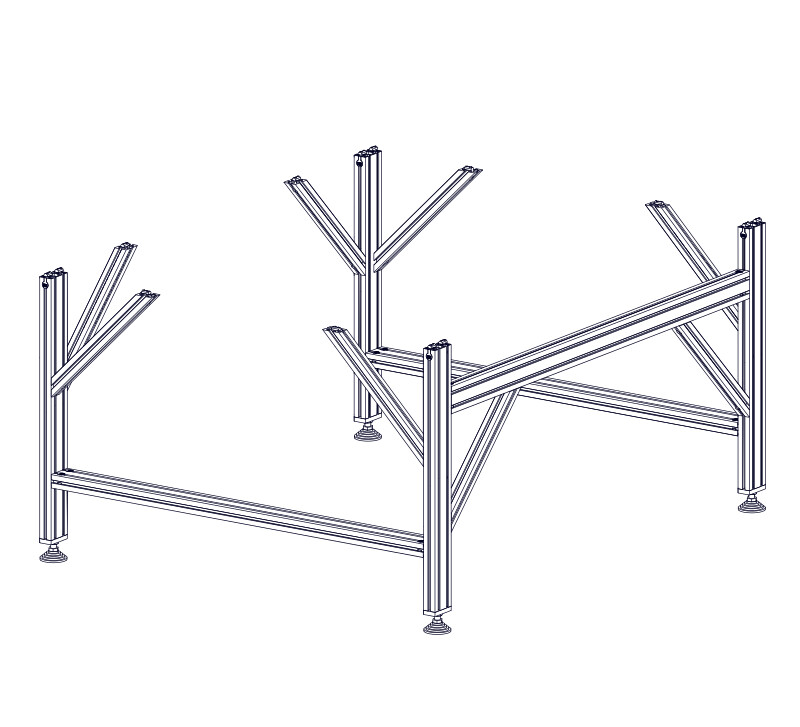
1.1.4.5
- At the top of the indicated legs, partially thread M8 x 30mm Socket Head Cap Screws E into M8 Roll-in T-Nuts G through 40 Series Anchor Fasteners D .
1.1.4.6


- Repeat the previous step to install anchor fasteners on the remaining leg assemblies.
| ID | QTY | Part/Description | Package Label |
|---|---|---|---|
A | 2 2 2 2 2 2 2 4 4 | 4080 Frame Extrusion, 950mm (37-3/8") 4080 Frame Extrusion, 1250mm (49-1/4") 4080 Frame Extrusion, 1600mm (63") 4080 Frame Extrusion, 1900mm (74-13/16") 4080 Frame Extrusion, 1900mm (74-13/16") 4080 Frame Extrusion, 2200mm (86-5/8") 4080 Frame Extrusion, 2000mm (78-3/4") 4080 Frame Extrusion, 1750mm (68-7/8") 4080 Frame Extrusion, 2200mm (86-5/8") 4080 Frame Extrusion, 2375mm (93-1/2") 4080 Frame Extrusion, 2525mm (99-3/8") 4080 Frame Extrusion, 2600mm (102-3/8") 4080 Frame Extrusion, 2700mm (106-5/16") 4080 Frame Extrusion, 3000mm (118-1/8") 4080 Frame Extrusion, 3250mm (127-15/16") 4080 Frame Extrusion, 3250mm (127-15/16") 4080 Frame Extrusion, 3300mm (129-15/16") 4080 Frame Extrusion, 3300mm (129-15/16") 4080 Frame Extrusion, 3500mm (137-13/16") 4080 Frame Extrusion, 4000mm (157-1/2") | Machine Kit Extrusion |
B | 2 2 4 6 2 | 4080 Frame Extrusion, 1250mm (49-1/4") 4080 Frame Extrusion, 1600mm (63") 4080 Frame Extrusion, 1900m (74-13/16") 4080 Frame Extrusion, 2200mm (86-5/8") 4080 Frame Extrusion, 2500mm (98-7/16") 4080 Frame Extrusion, 2750mm (108-1/4") 4080 Frame Extrusion, 2850mm (112-3/16") | Machine Kit Extrusion |
B | 2 2 4 | 4080 Frame Extrusion, 2400mm (94-1/2") 4080 Frame Extrusion, 2850mm (112-3/16") 4080 Frame Extrusion, 3000mm (118-1/8") 4080 Frame Extrusion, 3250mm (127-15/16") 4080 Frame Extrusion, 3300mm (129-15/16") | Machine Kit Extrusion |
B | 2 | 4080 Frame Extrusion, 2400mm (94-1/2") 4080 Frame Extrusion, 2700mm (106-5/16") 4080 Frame Extrusion, 3850mm (151-9/16") | Machine Kit Extrusion |
C | 2 4 | 4080 Frame Extrusion, 1750mm (68-7/8") 4080 Frame Extrusion, 2750mm (108-1/4") 4080 Frame Extrusion, 3000mm (118-1/8") 4080 Frame Extrusion, 3300mm (129-15/16") | Machine Kit Extrusion |
C | 2 4 | 4080 Frame Extrusion, 2700mm (106-5/16") | Machine Kit Extrusion |
D | 2 | 4080 Frame Extrusion, 3000mm (118-1/8") 4080 Frame Extrusion, 3050mm (127-15/16") 4080 Frame Extrusion, 3300mm (129-15/16") | Machine Kit Extrusion |
E | 3 4 5 6 7 8 9 10 11 12 13 14 15 16 17 18 19 20 21 22 23 24 25 26 27 28 29 30 31 32 33 | 4080 Table Crossmember Extrusion, 650mm (25-9/16") 4080 Table Crossmember Extrusion, 950mm (37-3/8") 4080 Table Crossmember Extrusion, 1250mm (49-1/4") 4080 Table Crossmember Extrusion, 1550mm (61") 4080 Table Crossmember Extrusion, 1850mm (72-13/16") 4080 Table Crossmember Extrusion, 2200mm (86-5/8") 4080 Table Crossmember Extrusion, 2500mm (98-7/16") | Machine Kit Extrusion |
1 | 40 Series Short Double Anchor Assembly - 24 40 Series Short Double Anchor Assembly - 36 40 Series Short Double Anchor Assembly - 48 40 Series Short Double Anchor Assembly - 60 40 Series Short Double Anchor Assembly - 72 40 Series Short Double Anchor Assembly - 84 40 Series Short Double Anchor Assembly - 96 40 Series Short Double Anchor Assembly - 108 40 Series Short Double Anchor Assembly - 120 40 Series Short Double Anchor Assembly - 132 40 Series Short Double Anchor Assembly - 144 40 Series Short Double Anchor Assembly - 156 40 Series Short Double Anchor Assembly - 168 40 Series Short Double Anchor Assembly - 180 40 Series Short Double Anchor Assembly - 192 40 Series Short Double Anchor Assembly - 204 40 Series Short Double Anchor Assembly - 216 40 Series Short Double Anchor Assembly - 228 40 Series Short Double Anchor Assembly - 240 40 Series Short Double Anchor Assembly - 252 40 Series Short Double Anchor Assembly - 264 40 Series Short Double Anchor Assembly - 276 40 Series Short Double Anchor Assembly - 288 40 Series Short Double Anchor Assembly - 300 40 Series Short Double Anchor Assembly - 312 40 Series Short Double Anchor Assembly - 324 40 Series Short Double Anchor Assembly - 336 40 Series Short Double Anchor Assembly - 348 40 Series Short Double Anchor Assembly - 360 40 Series Short Double Anchor Assembly - 372 40 Series Short Double Anchor Assembly - 384 40 Series Short Double Anchor Assembly - 396 40 Series Short Double Anchor Assembly - 408 40 Series Short Double Anchor Assembly - 420 40 Series Short Double Anchor Assembly - 432 40 Series Short Double Anchor Assembly - 444 40 Series Short Double Anchor Assembly - 456 40 Series Short Double Anchor Assembly - 468 40 Series Short Double Anchor Assembly - 480 40-3100-00 | Base Hardware | |
F | 40 Series Anchor Fastener | 40-3100-00Packaged in | |
G | M8 x 30mm Socket Head Cap Screw | 40-3100-00Packaged in | |
H | M8 Double Anchor Slide-in T-Nut CRP810-01 | 40-3100-00Packaged in | |
CRP813-00-LEGSET-HW-BAG-21.1 | Base Hardware | ||
I | M8 x 16mm Socket Head Cap Screw (4 per bag) | CRP813-00-LEGSET-HW-BAG-21.1Packaged in | |
J | M8 Roll-in T-Nut (12 per bag) | CRP813-00-LEGSET-HW-BAG-21.1Packaged in | |
K | Leg Gusset CRP813-02 | Leg Extrusion | |
1 | PRO Splice Kit CRP810-00-SP-21.1 | Base Hardware | |
L | 2 4 | Splice Bar CRP810-02 | CRP810-00-SP-21.1Packaged in |
L | Splice Bar CRP810-02 | CRP810-00-SP-21.1Packaged in | |
M | 12 28 | M8 x 8mm Set Screw | CRP810-00-SP-21.1Packaged in |
M | M8 x 8mm Set Screw | CRP810-00-SP-21.1Packaged in |
Tools List
| Requirement | Tool |
|---|---|
| Required | 4mm Ball-End Allen Wrench |
| Required | 6mm Ball-End Allen Wrench |
| Required | Tape Measure |
| Recommended | 6mm Hex Ball-End Power Bit |
| Recommended | Dimensional Lumber |
| Recommended | (2) 24" Hand Trigger Clamp |
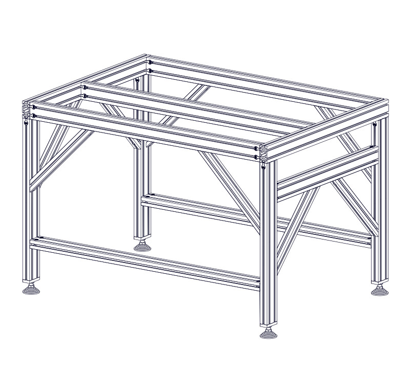
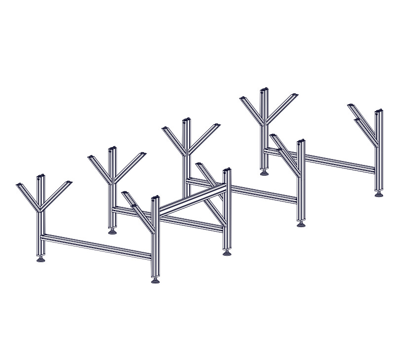
1.2.1 - Frame Extrusion Installation
1.2.1.1
- Slide two 4080 Frame Extrusion, 950mm (37-3/8") 1250mm (49-1/4") 1600mm (63") 1900mm (74-13/16") A onto the leg assemblies as indicated.
1.2.1.2
- Slide two 4080 Frame Extrusion, 1750mm (68-7/8") 1900mm (74-13/16") 2000mm (78-3/4") A onto the leg assemblies as indicated.
1.2.1.3
- Slide two 4080 Frame Extrusion, 2200mm (86-5/8") 2375mm (93-1/2") 2525mm (99-3/8") 2200mm (86-5/8") 2200mm (86-5/8") A onto the leg assemblies as indicated.
Assembly Note
If your frame extrusion is split evenly and your kit contains 4x 4080 Frame Extrusion, 2050mm (74-13/16") the following instructions still apply.
1.2.1.4
- Slide two 4080 Frame Extrusion, 1600mm (63") B onto the back of the leg assembly as indicated.
1.2.1.5
- Thread M8 x 8mm Set Screws M into Splice Bars L and slide them into the extrusion at the indicated locations.
1.2.1.6

- Position the splice bars as shown and fully tighten the indicated set screws.
Assembly Note
Tighten the set screws on both the upper and lower splice bars.
1.2.1.7
- Slide two 4080 Frame Extrusion, 950mm (37-3/8") A onto the front of the leg assembly.
1.2.1.8

- Bring the ends of the extrusion pieces tight against each other.
- Tighten all remaining splice bar set screws.
1.2.1.9
- Slide two 4080 Frame Extrusion, 1600mm (63") A onto the leg assemblies as indicated.
Assembly Note
Note the orientation of the leg assemblies with the splice bar at the back.
1.2.1.10
- Slide two 4080 Frame Extrusion, 2600mm (102-3/8") 2700mm (106-5/16") 3000mm (118-1/8") 3500mm (137-13/16") A onto the leg assemblies as indicated.
1.2.1.11
- Slide two 4080 Frame Extrusion, 3000mm (118-1/8") 3250mm (127-15/16") 3250mm (127-15/16") 3300mm (129-15/16") A onto the leg assemblies as indicated.
1.2.1.12
- Slide two 4080 Frame Extrusion, 3300mm (129-15/16") 4000mm (157-1/2") A onto the leg assemblies as indicated.
1.2.1.13


- Bring the ends of the frame extrusion flush with the legs.
- Partially tighten the anchor fasteners attaching the frame extrusion to the legs.
1.2.1.14


- Bring the ends of the frame extrusion flush with the front legs.
- Partially tighten the anchor fasteners on the indicated legs.
1.2.1.15


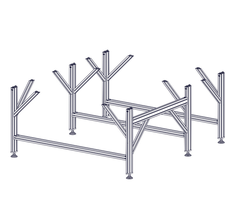
- Position the leg assemblies 1160mm (45-11/16") apart.
Assembly Note
The dimension shown is measured from the front edge of each leg section.
1.2.1.16


- Partially tighten the anchor fasteners at the indicated locations.
1.2.1.17


- Slide the third leg assembly onto the frame extrusion.
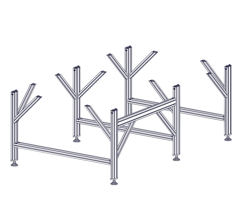
1.2.1.18


- Bring the legs flush with the ends of the frame extrusion and partially tighten the anchor fasteners.
1.2.1.19

- Position the frame extrusion 400mm (157-1/2") from the front legs.
- Partially tighten the anchor fasteners on the indicated legs.
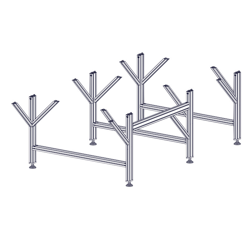
1.2.1.20
- Thread M8 x 8mm Set Screws M into Splice Bars L and slide them into the extrusion at the indicated locations.
1.2.1.21

- Position the splice bars as shown and fully tighten the indicated set screws.
1.2.1.22
- Slide the 4080 Frame Extrusion, 1250mm (49-1/4") B onto the splice bars.
Assembly Note
While the assembly will stand upright in the absence of applied force, be careful not to tip the assembly over.
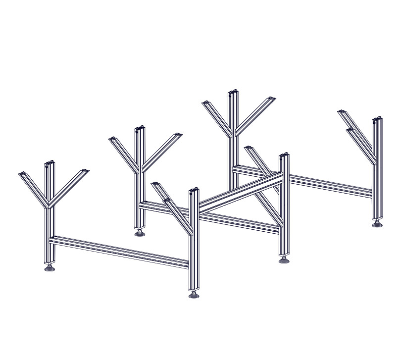
1.2.1.23

- Slide the last leg assembly onto the frame extrusion.
1.2.1.24

- Position the legs flush with the end of the frame extrusion.
- Partially tighten the anchor fasteners on the indicated legs.
1.2.1.25

- Bring the ends of the two frame extrusion pieces tight against each other.
- Tighten the indicated splice bar set screws on each side of the machine.
1.2.1.26
At the indicated locations, thread M8 x 8mm Set Screws M into the bottom splice bars.
Assembly Note
These set screws will be tightened in the next step.
1.2.1.27

- Position the middle leg to the dimension shown.
- Partially tighten the remaining leg anchor fasteners and splice bar set screws.
Assembly Note
The dimension shown is measured from inside edge to inside edge of the leg extrusion.
1.2.1.28


- Position the frame extrusion 400mm (157-1/2") from the front legs.
- Partially tighten the anchor fasteners on the indicated legs.
1.2.1.29


- Position the leg assemblies 1080mm (42-1/2") apart.
- Partially tighten the anchor fasteners on the indicated legs.
Assembly Note
The dimension shown is measured from inside edge to inside edge of the leg extrusion.
1.2.1.30
- Thread M8 x 8mm Set Screws M into Splice Bars L and slide them into the extrusion at the indicated locations
Assembly Note
Use the t-slots on the top and bottom of the extrusion.
1.2.1.31

- Position the splice bars as shown and fully tighten the indicated set screws on both upper and lower splice bars.
1.2.1.32
- Slide the 4080 Frame Extrusion 1900mm (74-13/16") A 4080 Frame Extrusion 1900mm (74-13/16") B 4080 Frame Extrusion 2400mm (94-1/2") B 4080 Frame Extrusion 2375mm (93-1/2") A 4080 Frame Extrusion 2525mm (99-3/8") A 4080 Frame Extrusion 2700mm (106-5/16") A 4080 Frame Extrusion 2200mm (86-5/8") A 4080 Frame Extrusion 2500mm (98-7/16") B 4080 Frame Extrusion 2850mm (112-3/16") B onto the third leg assembly and then onto the splice bars.
1.2.1.33
- Slide the 4080 Frame Extrusion, 1250mm (49-1/4") A 4080 Frame Extrusion, 1600mm (63") B onto the splice bars.
Assembly Note
While the assembly will stand upright in the absence of applied force, be careful not to tip the assembly over.
1.2.1.34


- Slide the third leg assembly onto the frame extrusion.
1.2.1.35


- Bring the ends of the two frame extrusion pieces tight against each other.
- Tighten all remaining splice bar set screws.
1.2.1.36
- Slide the remaining leg assembly onto the frame extrusion.
- Slide a leg assembly onto the frame extrusion.

1.2.1.38

- Position the frame extrusion 400mm (157-1/2") from the front legs.
- Partially tighten the anchor fasteners on the indicated legs.
1.2.1.39

- Position the leg assemblies 1080mm (42-1/2") apart.
- Partially tighten the anchor fasteners on the indicated legs.
1.2.1.40

- Slide the third leg assembly onto the frame extrusion.
1.2.1.41

- Position the legs flush with the end of the frame extrusion.
- Partially tighten the anchor fasteners on the indicated legs.
1.2.1.42

- Position the remaining leg assemblies 1120mm (44-3/32") apart.
- Partially tighten the anchor fasteners on the remaining leg assemblies.
Assembly Note
The dimension shown is measured from inside edge to inside edge of the leg extrusion.
1.2.1.43

- Slide the fourth leg assembly onto the frame extrusion.
1.2.1.44

- Position the remaining leg assemblies 1120mm (44-3/32") apart, except the last leg assembly which is flush with the frame extrusion at the back of the machine.
- Partially tighten the anchor fasteners on the remaining leg assemblies.
Assembly Note
The dimension shown is measured from inside edge to inside edge of the leg extrusion.
1.2.1.45

- Position each remaining leg assembly 1120mm (44-3/32") apart, except the last leg assembly which is flush with the frame extrusion at the back of the machine.
- Partially tighten all remaining anchor fasteners attaching the legs to the table extrusion.
Assembly Note
When a leg assembly is positioned close to a frame extrusion splice, it may be necessary to slightly adjust the position of the lower splice bar.
1.2.1.46


- Slide an additional leg assembly onto the frame extrusion.
Assembly Note
Use the leg assembly with anchor fasteners, not splice bars.
1.2.1.47

- Position the frame extrusion 400mm (157-1/2") from the front legs.
- Partially tighten the anchor fasteners on the indicated legs.
1.2.1.48

- Position the first two leg assemblies 1080mm (42-1/2") apart.
- Partially tighten the anchor fasteners on the indicated legs.
1.2.1.49
- Thread M8 x 8mm Set Screws M into Splice Bars L and slide them into the extrusion at the indicated locations.
Assembly Note
Use the t-slots on the top and bottom of the extrusion.
1.2.1.50


- Slide the leg assembly with splice bars onto the frame extrusion.
1.2.1.51
- Thread M8 x 8mm Set Screws M into Splice Bars L and slide them into the extrusion at the indicated locations.
1.2.1.52
- Position the splice bars as shown and fully tighten the indicated set screws.
1.2.1.53
- Slide the 4080 Frame Extrusion 2500mm (98-7/16") B 4080 Frame Extrusion 4000mm (157-1/2") A onto an additional leg assembly, then onto the splice bars.
1.2.1.54


- Bring the ends of the two frame extrusion pieces tight against each other.
- Tighten the set screws on the upper splice bars.
1.2.1.55
- At the indicated locations, thread M8 x 8mm Set Screws M into the bottom splice bars.
Assembly Note
These set screws will be tightened in a future step.
1.2.1.56


- Slide the remaining leg assembly onto the frame extrusion.
- Slide all remaining leg assemblies onto the frame extrusion.
1.2.1.57
- Position each remaining leg assembly 1120mm (44-3/32") apart, except the last leg assembly which is flush with the frame extrusion at the back of the machine.
- Partially tighten all remaining anchor fasteners attaching the legs to the table extrusion.
1.2.1.58
- Position the splice bars as shown and fully tighten the indicated set screws on both upper and lower splice bars.
1.2.1.59
- Slide the 4080 Frame Extrusion 3850mm (151-9/16") A 4080 Frame Extrusion 2200mm (86-5/8") B 4080 Frame Extrusion 2400mm (94-1/2") B 4080 Frame Extrusion 2700mm (106-5/16") B 4080 Frame Extrusion 3000mm (118-1/8") A 4080 Frame Extrusion 3000mm (118-1/8") B 4080 Frame Extrusion 3250mm (127-15/16") B 4080 Frame Extrusion 3300mm (129-15/16") B 4080 Frame Extrusion 3850mm (151-9/16") B onto an additional leg assembly and then onto the splice bars.
1.2.1.60

- Bring the ends of the two frame extrusion pieces tight against each other.
- Tighten all remaining splice bar set screws.
1.2.1.61


- Slide all remaining leg assemblies onto the frame extrusion.
1.2.1.62
- Position each remaining leg assembly 1120mm (44-3/32") apart, except the last leg assembly which is flush with the frame extrusion at the back of the machine.
- Partially tighten all remaining anchor fasteners attaching the legs to the table extrusion.
1.2.1.63

- Remaining leg assembles will be positioned 1120mm (44-3/32") apart, except the last leg assembly which is flush with the frame extrusion at the back of the machine.
- After positioning a leg assembly, partially tighten the anchor fasteners attaching it to the frame extrusion.
1.2.1.64
- Using splice bars, install the 4080 Frame Extrusion, 3300mm (129-15/16") A 4080 Frame Extrusion, 2750mm (108-1/4") B 4080 Frame Extrusion, 2850mm (112-3/16") B 4080 Frame Extrusion, 3300mm (129-15/16") B 4080 Frame Extrusion, 2700mm (106-5/16") C 4080 Frame Extrusion, 3000mm (118-1/8") C 4080 Frame Extrusion, 3300mm (129-15/16") C and all remaining leg assemblies.
1.2.1.65
- Remaining leg assembles will be positioned 1120mm (44-3/32") apart, except the last leg assembly which is flush with the frame extrusion at the back of the machine.
- After positioning a leg assembly, partially tighten the anchor fasteners attaching it to the frame extrusion.
1.2.1.66
- Using splice bars, install the 4080 Frame Extrusion, 2700mm (106-5/16") C 4080 Frame Extrusion, 2750mm (108-1/4") C 4080 Frame Extrusion, 2850mm (112-3/16") B and all remaining leg assemblies.
- Using splice bars, install the 4080 Frame Extrusion, 2700mm (106-5/16") C , 4080 Frame Extrusion, 2750mm (108-1/4") C , 4080 Frame Extrusion, 3000mm (118-1/8") D , 4080 Frame Extrusion, 3300mm (129-15/16") A , 4080 Frame Extrusion, 3050mm (127-15/16") D , 4080 Frame Extrusion, 3300mm (129-15/16") D , and all remaining leg assemblies.
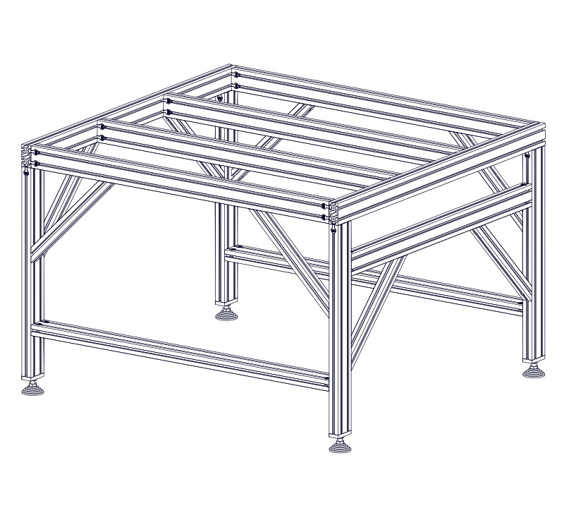
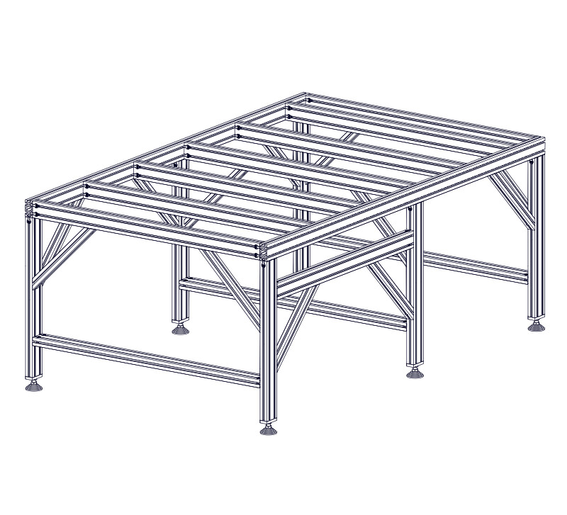
1.2.2 - Table Crossmember Assembly
1.2.2.1
- Install M8 x 30mm Socket Head Cap Screws G and 40 Series Anchor Fasteners F into a 4080 Table Crossmember Extrusion, 650mm (25-9/16") E . 4080 Table Crossmember Extrusion, 950mm (37-3/8") E . 4080 Table Crossmember Extrusion, 1250mm (49-1/4") E . 4080 Table Crossmember Extrusion, 1550mm (61") E . 4080 Table Crossmember Extrusion, 1850mm (72-13/16") E . 4080 Table Crossmember Extrusion, 2200mm (86-5/8") E . 4080 Table Crossmember Extrusion, 2500mm (98-7/16") E .
1.2.2.2
- Loosely thread M8 Double Anchor Slide-in T-Nuts H onto the socket head cap screws.
1.2.2.3


- Repeat the previous two steps to install anchor fasteners on both sides of all table crossmembers.
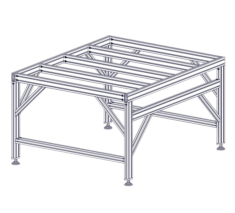
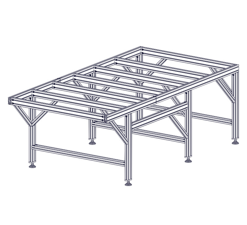
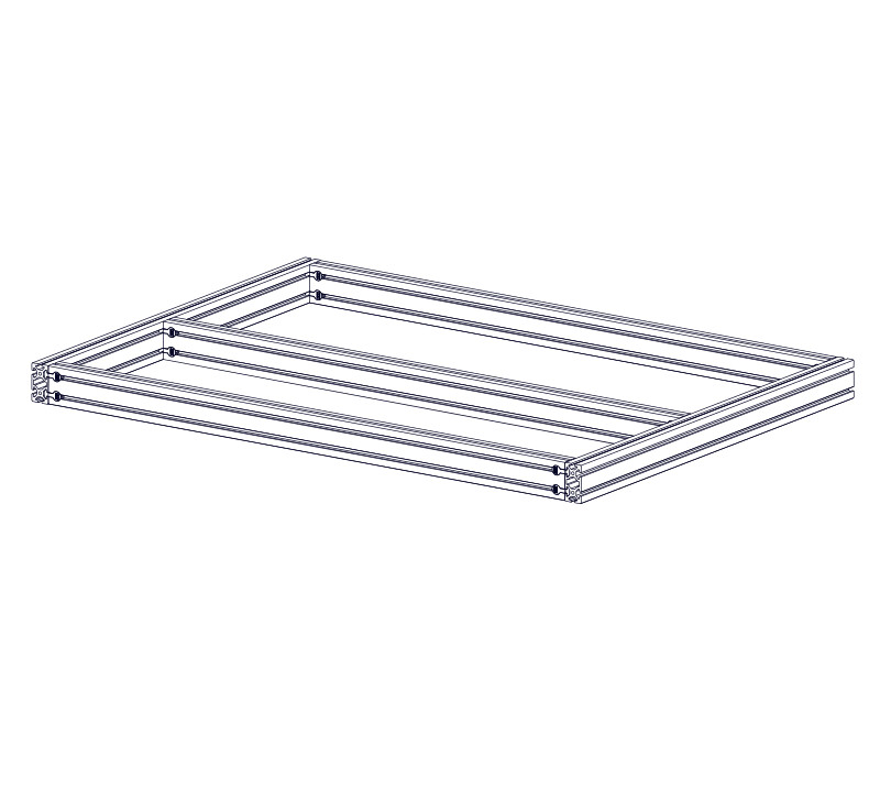
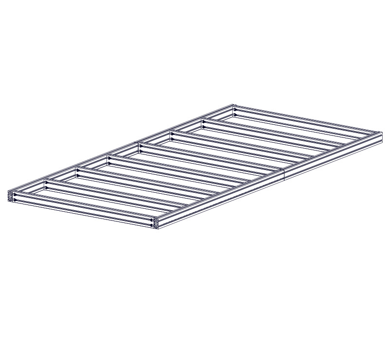
1.2.3 - Table Crossmember Installation
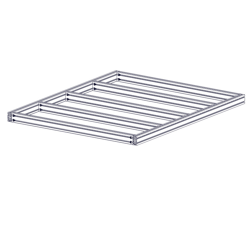
1.2.3.1


- Slide a crossmember assembly onto the frame extrusion.
1.2.3.2


- Repeat the previous step for all crossmembers.
1.2.3.3

- Position the outer crossmembers flush with the ends of the frame extrusion.
- Position the crossmembers 360mm (14-3/16") apart (or 400mm (15-3/4") center to center).
Assembly Note
Use dimensional lumber to help position the crossmembers, as shown in the following steps.
1.2.3.4


- Cut two pieces of dimensional lumber (a 2x4 is recommended) to a length of 360mm (14-3/16").
- Position this piece between the crossmembers as indicated.
1.2.3.5


- With the cut piece of lumber flush against the frame extrusion, clamp the crossmembers together.
Assembly Note
Recommended clamps are 24" Hand Trigger Clamps available at your local hardware store.
1.2.3.6


- Repeat this process to clamp the other side of the crossmember.
- While clamped, tighten the crossmember anchor fasteners.
1.2.3.7


- Repeat this process to position the remaining crossmembers, except the rear crossmember which is positioned flush against the end of the frame extrusion.
Assembly Note
The rear crossmember will have a different spacing due to the length of the machine.
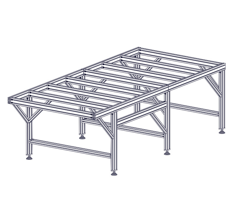
1.2.3.8
- Attach a Leg Gusset K between the leg and table crossmember using M8 x 16mm Socket Head Cap Screws I and M8 Roll-in T-Nuts J .
Assembly Note
The front crossmember is hidden for illustrative purposes.
1.2.3.9


- With each end of the gusset flush with the mating extrusion, partially tighten the gusset fasteners.
1.2.3.10


- Use this procedure to install two gussets at each corner of the machine.
- Use this procedure to install two gussets at on each leg.
Assembly Note
The leg gussets on the middle leg assembly are oriented towards the front of the machine.
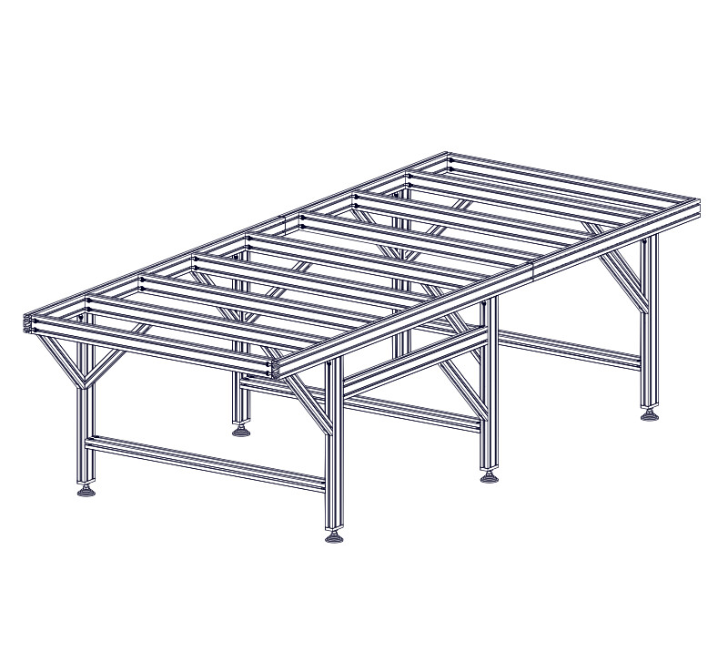
1.2.3.11

- Use this procedure to install a leg gusset between the leg and frame extrusion.
1.2.3.12


- Install two leg gussets on each of the remaining legs:
- One gusset between the leg and table crossmember extrusion.
- One gusset between the leg and frame extrusion. These gussets are oriented towards the front of the machine.
Assembly Note
One leg gusset will attach to the electronics bar extrusion, as shown.
Assembly Note
When attaching the gusset to the frame extrusion, if there is interference with the splice bar, adjust the splice bar position to allow attachment of the gusset.
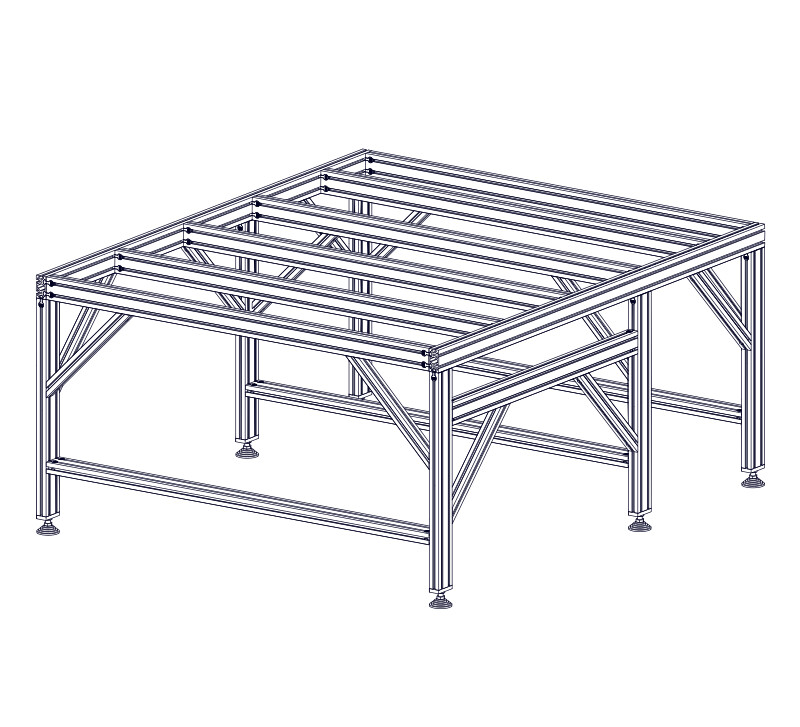
1.2.4 - Table Squaring
1.2.4.1


- Measure diagonal across the table in each direction as indicated.
- Make adjustments until the two measurements are within 1/8" or less of each other.
- After squaring the table, tighten all anchor fasteners, splice bar set screws, and leg gusset fasteners.
Assembly Note
Position of the leg gussets may need to be adjusted in the table squaring process.
| ID | QTY | Part/Description | Package Label |
|---|---|---|---|
A | 2 2 2 2 2 4 4 | 4080 Frame Extrusion, 950mm (37-3/8") 4080 Frame Extrusion, 1250mm (49-1/4") 4080 Frame Extrusion, 1600mm (63") 4080 Frame Extrusion, 1750mm (68-7/8") 4080 Frame Extrusion, 1900mm (74-13/16") 4080 Frame Extrusion, 2000mm (78-3/4") 4080 Frame Extrusion, 2200mm (86-5/8") 4080 Frame Extrusion, 2375mm (93-1/2") 4080 Frame Extrusion, 2700mm (106-5/16") 4080 Frame Extrusion, 3250mm (127-15/16") 4080 Frame Extrusion, 3250mm (127-15/16") 4080 Frame Extrusion, 3300mm (129-15/16") 4080 Frame Extrusion, 3300mm (129-15/16") 4080 Frame Extrusion, 3500mm (137-13/16") 4080 Frame Extrusion, 4000mm (157-1/2") | Machine Kit Extrusion |
B | 2 2 4 6 | 4080 Frame Extrusion, 1250mm (49-1/4") 4080 Frame Extrusion, 1600mm (63") 4080 Frame Extrusion, 1900mm (74-13/16") 4080 Frame Extrusion, 2200mm (86-5/8") 4080 Frame Extrusion, 2500mm (98-7/16") 4080 Frame Extrusion, 2750mm (108-1/4") 4080 Frame Extrusion, 2850mm (112-3/16") | Machine Kit Extrusion |
B | 2 2 4 | 4080 Frame Extrusion, 2400mm (94-1/2") 4080 Frame Extrusion, 2525mm (99-3/8") 4080 Frame Extrusion, 2850mm (112-3/16") 4080 Frame Extrusion, 3000mm (118-1/8") 4080 Frame Extrusion, 3250mm (127-15/16") 4080 Frame Extrusion, 3300mm (129-15/16") | Machine Kit Extrusion |
B | 2 | 4080 Frame Extrusion, 2400mm (94-1/2") 4080 Frame Extrusion, 2700mm (106-5/16") 4080 Frame Extrusion, 3850mm (151-9/16") | Machine Kit Extrusion |
C | 2 4 | 4080 Frame Extrusion, 1750mm (68-7/8") 4080 Frame Extrusion, 2750mm (108-1/4") 4080 Frame Extrusion, 3000mm (118-1/8") 4080 Frame Extrusion, 3300mm (129-15/16") | Machine Kit Extrusion |
C | 2 4 | 4080 Frame Extrusion, 2700mm (106-5/16") | Machine Kit Extrusion |
D | 2 | 4080 Frame Extrusion, 3000mm (118-1/8") 4080 Frame Extrusion, 3050mm (127-15/16") 4080 Frame Extrusion, 3300mm (129-15/16") | Machine Kit Extrusion |
E | 3 4 5 6 7 8 9 10 11 12 13 14 15 16 17 18 19 20 21 22 23 24 25 26 27 28 29 30 31 32 33 | 4080 Table Crossmember Extrusion, 650mm (25-9/16") 4080 Table Crossmember Extrusion, 950mm (37-3/8") 4080 Table Crossmember Extrusion, 1250mm (49-1/4") 4080 Table Crossmember Extrusion, 1550mm (61") 4080 Table Crossmember Extrusion, 1850mm (72-13/16") 4080 Table Crossmember Extrusion, 2200mm (86-5/8") 4080 Table Crossmember Extrusion, 2500mm (98-7/16") | Machine Kit Extrusion |
1 | 40-3100-00 - 40 Series Short Double Anchor Assembly - 24 40-3100-00 - 40 Series Short Double Anchor Assembly - 36 40-3100-00 - 40 Series Short Double Anchor Assembly - 48 40-3100-00 - 40 Series Short Double Anchor Assembly - 60 40-3100-00 - 40 Series Short Double Anchor Assembly - 72 40-3100-00 - 40 Series Short Double Anchor Assembly - 84 40-3100-00 - 40 Series Short Double Anchor Assembly - 96 40-3100-00 - 40 Series Short Double Anchor Assembly - 108 40-3100-00 - 40 Series Short Double Anchor Assembly - 120 40-3100-00 - 40 Series Short Double Anchor Assembly - 132 40-3100-00 - 40 Series Short Double Anchor Assembly - 144 40-3100-00 - 40 Series Short Double Anchor Assembly - 156 40-3100-00 - 40 Series Short Double Anchor Assembly - 168 40-3100-00 - 40 Series Short Double Anchor Assembly - 180 40-3100-00 - 40 Series Short Double Anchor Assembly - 192 40-3100-00 - 40 Series Short Double Anchor Assembly - 204 40-3100-00 - 40 Series Short Double Anchor Assembly - 216 40-3100-00 - 40 Series Short Double Anchor Assembly - 228 40-3100-00 - 40 Series Short Double Anchor Assembly - 240 40-3100-00 - 40 Series Short Double Anchor Assembly - 252 40-3100-00 - 40 Series Short Double Anchor Assembly - 264 40-3100-00 - 40 Series Short Double Anchor Assembly - 276 40-3100-00 - 40 Series Short Double Anchor Assembly - 288 40-3100-00 - 40 Series Short Double Anchor Assembly - 300 40-3100-00 - 40 Series Short Double Anchor Assembly - 312 40-3100-00 - 40 Series Short Double Anchor Assembly - 324 40-3100-00 - 40 Series Short Double Anchor Assembly - 336 40-3100-00 - 40 Series Short Double Anchor Assembly - 348 40-3100-00 - 40 Series Short Double Anchor Assembly - 360 40-3100-00 - 40 Series Short Double Anchor Assembly - 372 40-3100-00 - 40 Series Short Double Anchor Assembly - 384 40-3100-00 - 40 Series Short Double Anchor Assembly - 396 40-3100-00 - 40 Series Short Double Anchor Assembly - 408 40-3100-00 - 40 Series Short Double Anchor Assembly - 420 40-3100-00 - 40 Series Short Double Anchor Assembly - 432 40-3100-00 - 40 Series Short Double Anchor Assembly - 444 40-3100-00 - 40 Series Short Double Anchor Assembly - 456 40-3100-00 - 40 Series Short Double Anchor Assembly - 468 40-3100-00 - 40 Series Short Double Anchor Assembly - 480 | Base Hardware | |
F | 40 Series Anchor Fastener | 40-3100-00Packaged in | |
G | M8 x 30mm Socket Head Cap Screw | 40-3100-00Packaged in | |
H | CRP810-01 M8 Double Anchor Slide-in T-Nut | 40-3100-00Packaged in | |
1 | CRP810-00-SP-21.1 - PRO Splice Kit | Base Hardware | |
I | CRP810-02 Splice Bar | CRP810-00-SP-21.1Packaged in | |
J | M8 x 8mm Set Screw | CRP810-00-SP-21.1Packaged in |
Tools List
| Requirement | Tool |
|---|---|
| Required | 3mm Ball-End Allen Wrench |
| Required | 6mm Ball-End Allen Wrench |
| Required | Tape Measure |
| Recommended | 6mm Hex Ball-End Power Bit |
| Recommended | Dimensional Lumber |
| Recommended | (2) 24" Hand Trigger Clamp |
1.3.1 - Table Crossmember Assembly
1.3.1.1
- Install M8 x 30mm Socket Head Cap Screws G and 40 Series Anchor Fasteners F into a 4080 Table Crossmember Extrusion, 650mm (25-9/16") E . 4080 Table Crossmember Extrusion, 950mm (37-3/8") E . 4080 Table Crossmember Extrusion, 1250mm (49-1/4") E . 4080 Table Crossmember Extrusion, 1550mm (61") E . 4080 Table Crossmember Extrusion, 1850mm (72-13/16") E . 4080 Table Crossmember Extrusion, 2200mm (86-5/8") E . 4080 Table Crossmember Extrusion, 2500mm (98-7/16") E .
1.3.1.2
- Loosely thread M8 Double Anchor Slide-in T-Nuts H onto the socket head cap screws.
1.3.1.3
- Repeat the previous two steps to install anchor fasteners on both sides of all table crossmembers.
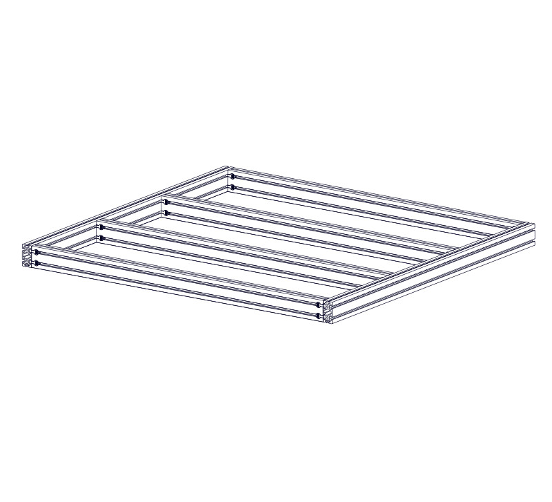
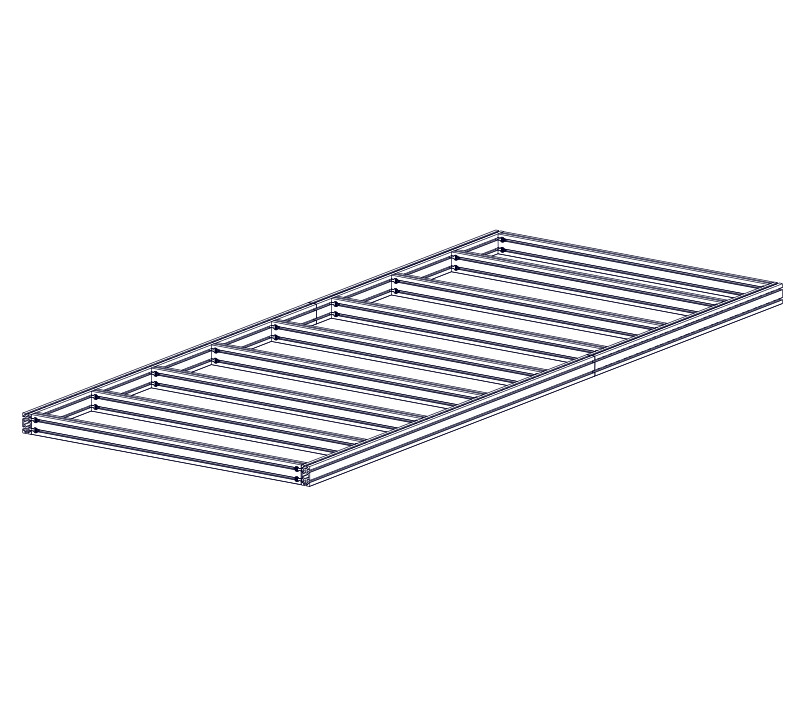
1.3.2 - Table Crossmember Installation
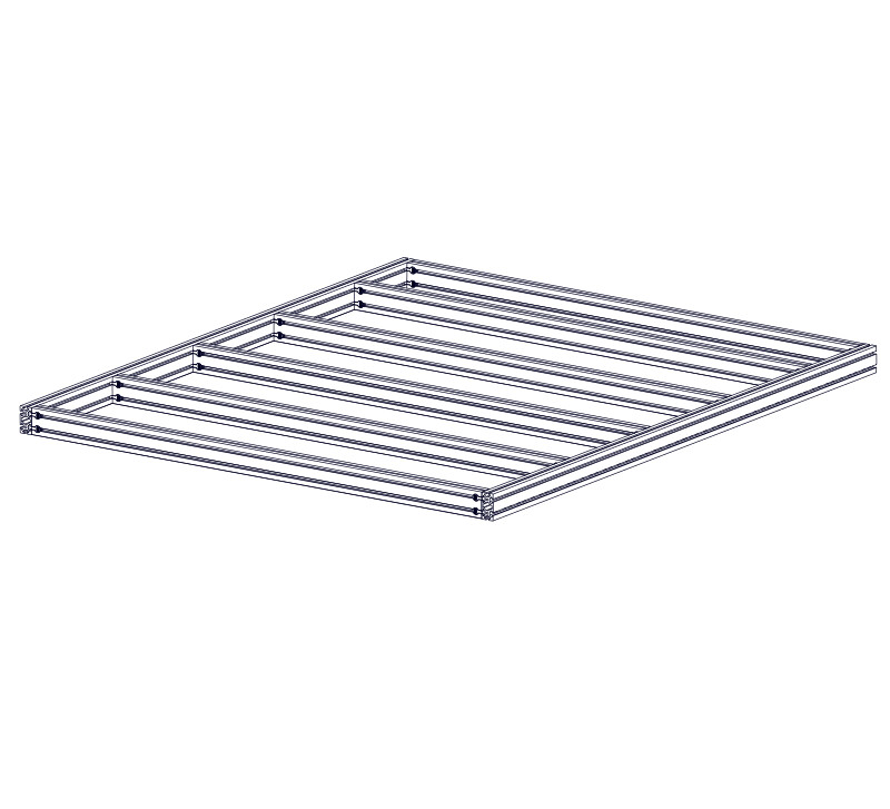
1.3.2.1
- Slide a crossmember assembly into the 4080 Frame Extrusion, 950mm (37-3/8") 1250mm (49-1/4") 1600mm (63") 1900mm (74-13/16") 2200mm (86-5/8") A .
1.3.2.2


- Repeat the previous step for all table crossmembers.
1.3.2.3


- Position the outer crossmembers flush with the ends of the frame extrusion.
1.3.2.4
- Position the crossmembers 360mm (14-3/16") apart (or 400mm (15-3/4") center to center).
Assembly Note
Use dimensional lumber to help position the crossmembers, as shown in the following steps.
1.3.2.5

- Cut two pieces of dimensional lumber (a 2x4 is recommended) to a length of 360mm (14-3/16").
- Position this piece between the crossmembers, as indicated.
1.3.2.6

- With the cut piece of lumber flush against the frame extrusion, clamp the crossmembers together.
Assembly Note
Recommended clamps are 24" Hand Trigger Clamps available at your local hardware store.
1.3.2.7


- Repeat this process to clamp the other side of the crossmember.
- While clamped, tighten the crossmember anchor fasteners.
Assembly Note
Recommended clamps are 24" Hand Trigger Clamps available at your local hardware store.
1.3.2.8


- Position the rear crossmember flush against the end of the frame extrusion.
- Repeat this process to position the remaining crossmembers, except the rear crossmember which is positioned flush against the end of the frame extrusion.
Assembly Note
The rear crossmember will have a different spacing due to the length of the machine.
1.3.3 - Frame Extrusion Splice
1.3.3.1
- Using Splice Bars I and M8 x 8mm Set Screws J , join a 4080 Frame Extrusion, 950mm (37-3/8") A 4080 Frame Extrusion, 1600mm (63") A 4080 Frame Extrusion, 1750mm (68-7/8") A 4080 Frame Extrusion, 1900mm (74-13/16") A 4080 Frame Extrusion, 2000mm (78-3/4") A 4080 Frame Extrusion, 2200mm (86-5/8") A 4080 Frame Extrusion, 2700mm (106-5/16") A 4080 Frame Extrusion, 3000mm (118-1/8") A 4080 Frame Extrusion, 3250mm (127-15/16") A 4080 Frame Extrusion, 3250mm (127-15/16") A 4080 Frame Extrusion, 3300mm (129-15/16") A 4080 Frame Extrusion, 3300mm (129-15/16") A 4080 Frame Extrusion, 3500mm (137-13/16") A and 4080 Frame Extrusion, 1250mm (49-1/4") B . 4080 Frame Extrusion, 1600mm (63") B . 4080 Frame Extrusion, 1900mm (74-13/16") B . 4080 Frame Extrusion, 2200mm (86-5/8") B . 4080 Frame Extrusion, 2400mm (94-1/2") B . 4080 Frame Extrusion, 2525mm (99-3/8") B . 4080 Frame Extrusion, 2500mm (98-7/16") B . 4080 Frame Extrusion, 2700mm (106-5/16") B . 4080 Frame Extrusion, 2750mm (108-1/4") B . 4080 Frame Extrusion, 2850mm (112-3/16") B . 4080 Frame Extrusion, 3000mm (118-1/8") B . 4080 Frame Extrusion, 3250mm (127-15/16") B . 4080 Frame Extrusion, 3300mm (129-15/16") B . 4080 Frame Extrusion, 3850mm (151-9/16") B .
- Using Splice Bars I and M8 x 8mm Set Screws J , join two 4080 Frame Extrusion, 1750mm (68-7/8") A . 4080 Frame Extrusion, 2375mm (93-1/2") A . 4080 Frame Extrusion, 2200mm (86-5/8") A . 4080 Frame Extrusion, 2700mm (106-5/16") A . 4080 Frame Extrusion, 3850mm (151-9/16") A . 4080 Frame Extrusion, 4000mm (157-1/2") A .
1.3.3.2

- Position the splice bars as shown and fully tighten the set screws on both upper and lower splice bars.
1.3.3.3
- Using splice bars, join a 4080 Frame Extrusion, 3300mm (129-15/16") A 4080 Frame Extrusion, 2525mm (99-3/8") B 4080 Frame Extrusion, 2500mm (98-7/16") B 4080 Frame Extrusion, 2750mm (108-1/4") B 4080 Frame Extrusion, 2850mm (112-3/16") B 4080 Frame Extrusion, 3300mm (129-15/16") B 4080 Frame Extrusion, 2700mm (106-5/16") C 4080 Frame Extrusion, 3000mm (118-1/8") C 4080 Frame Extrusion, 3300mm (129-15/16") C to the extrusion from the previous step.
1.3.3.4
- Using splice bars, join an additional two 4080 Frame Extrusion, 2700mm (106-5/16") C 4080 Frame Extrusion, 2750mm (108-1/4") C 4080 Frame Extrusion, 2850mm (112-3/16") B to the extrusion from the previous step.
- Using splice bars, join a 4080 Frame Extrusion, 2700mm (106-5/16") C 4080 Frame Extrusion, 2750mm (108-1/4") C and 4080 Frame Extrusion, 3000mm (118-1/8") D 4080 Frame Extrusion, 3300mm (129-15/16") A 4080 Frame Extrusion, 3050mm (127-15/16") D 4080 Frame Extrusion, 3300mm (129-15/16") D to the extrusion from the previous step.
1.3.3.5


- Use this process to form two spliced frame extrusion sections.
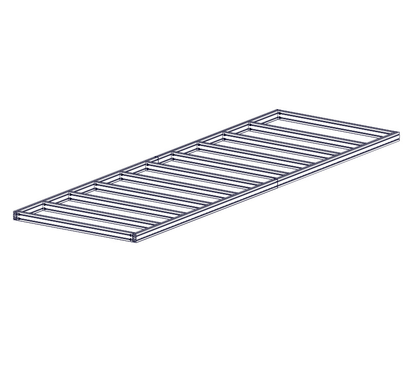
1.3.4 - Table Crossmember Installation
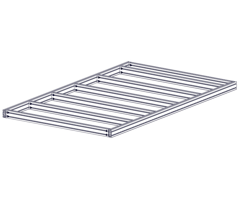
1.3.4.1


- Slide a crossmember assembly into the frame extrusion sections.
1.3.4.2


- Repeat the previous step for all crossmembers.
1.3.4.3
- Position the outer crossmembers flush with the ends of the frame extrusion.
1.3.4.4
- Position the crossmembers 360mm (14-3/16") apart (or 400mm (15-3/4") center to center).
Assembly Note
Use dimensional lumber to help position the crossmembers, as shown in the following steps.
1.3.4.5
- Cut two pieces of dimensional lumber (a 2x4 is recommended) to a length of 360mm (14-3/16").
- Position this piece between the crossmembers, as indicated.
1.3.4.6
- With the cut piece of lumber flush against the frame extrusion, clamp the crossmembers together.
Assembly Note
Recommended clamps are 24" Hand Trigger Clamps available at your local hardware store.
1.3.4.7
- Repeat this process to clamp the other side of the crossmember.
- While clamped, tighten the crossmember anchor fasteners.
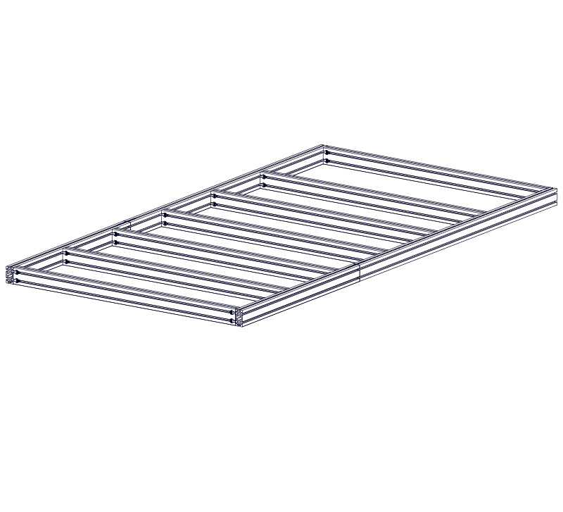
1.3.4.8

- Repeat this process to position the remaining crossmembers, except the rear crossmember which is positioned flush against the end of the frame extrusion.
Assembly Note
The rear crossmember will have a different spacing due to the length of the machine.
1.3.5 - Table Squaring
1.3.5.1
- Measure diagonal across the table in each direction as indicated.
- Make adjustments until the two measurements are within 1/8" or less of each other.
- After squaring the table, tighten all anchor fasteners, splice bar set screws, and leg gusset fasteners.