2. Base Components
Section Note
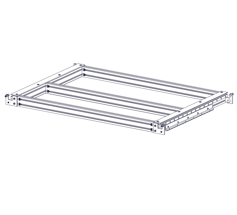
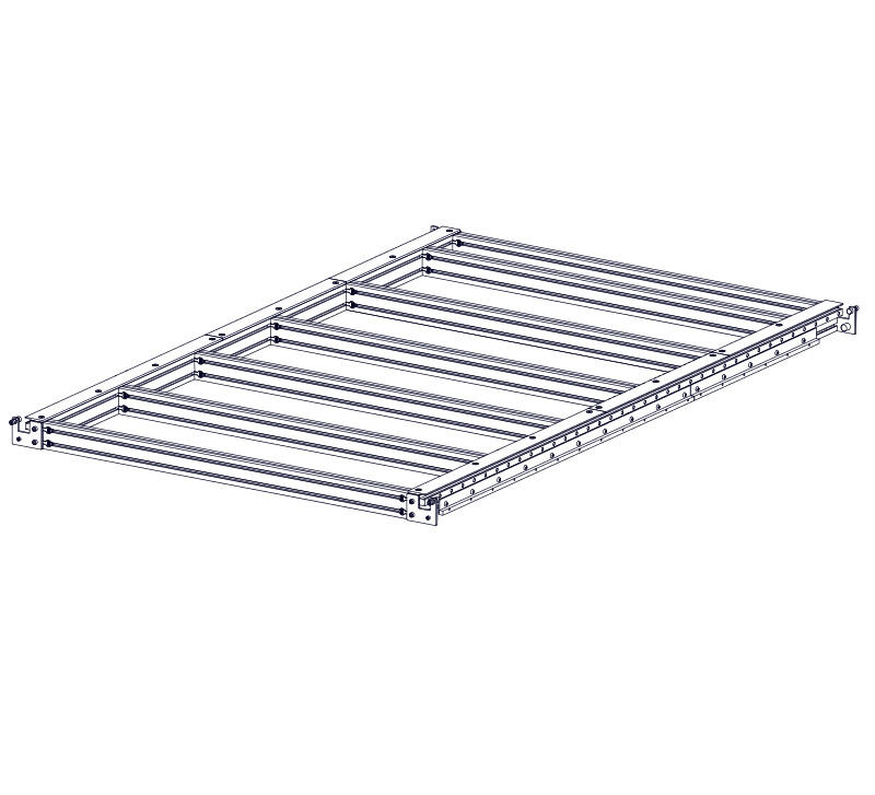
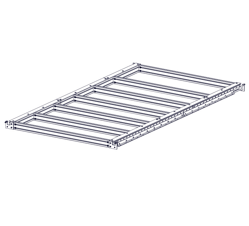
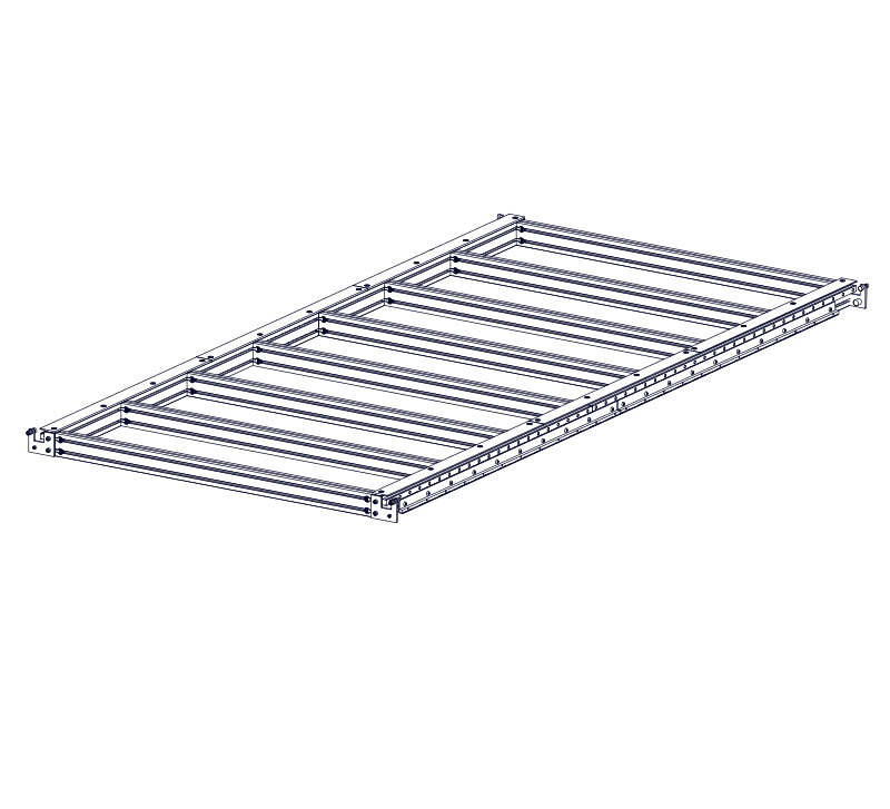
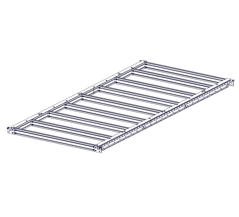
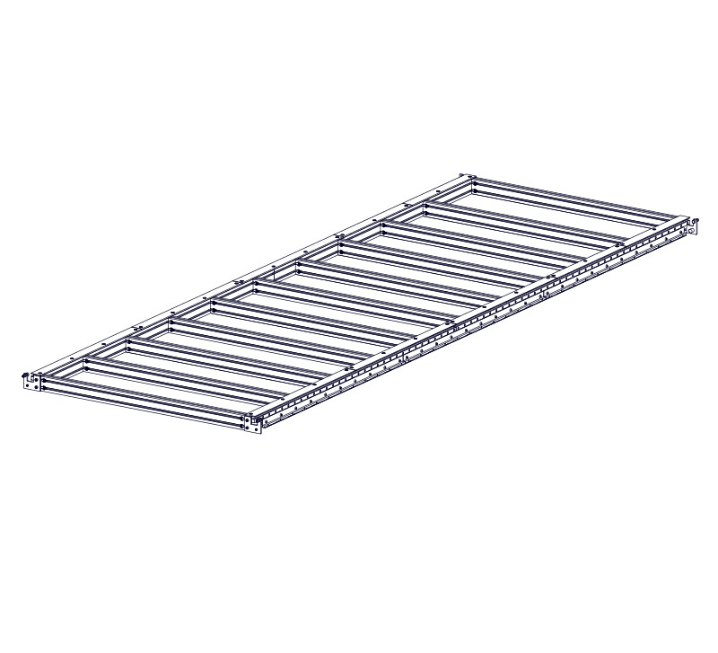
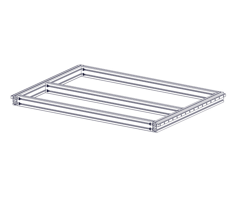
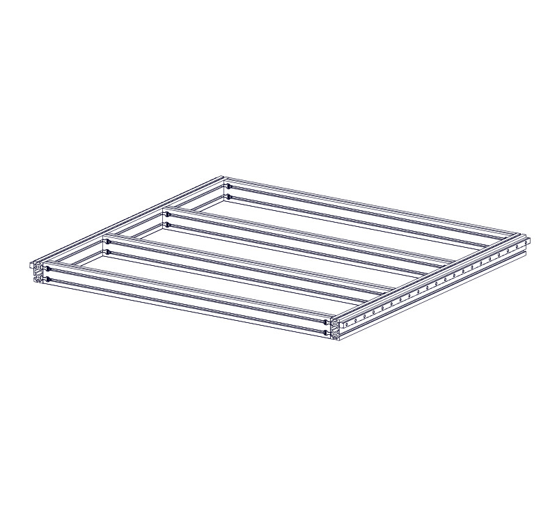
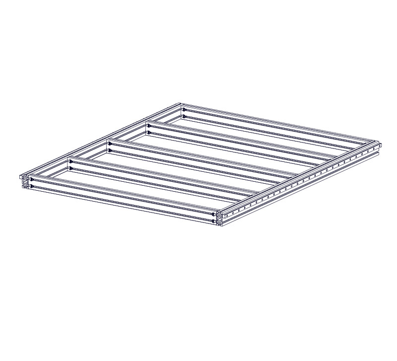
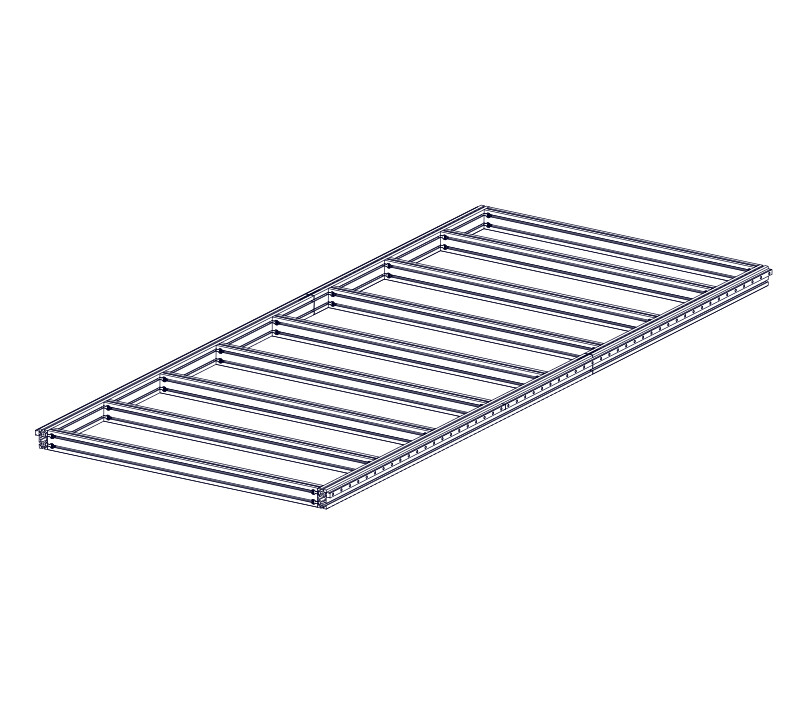
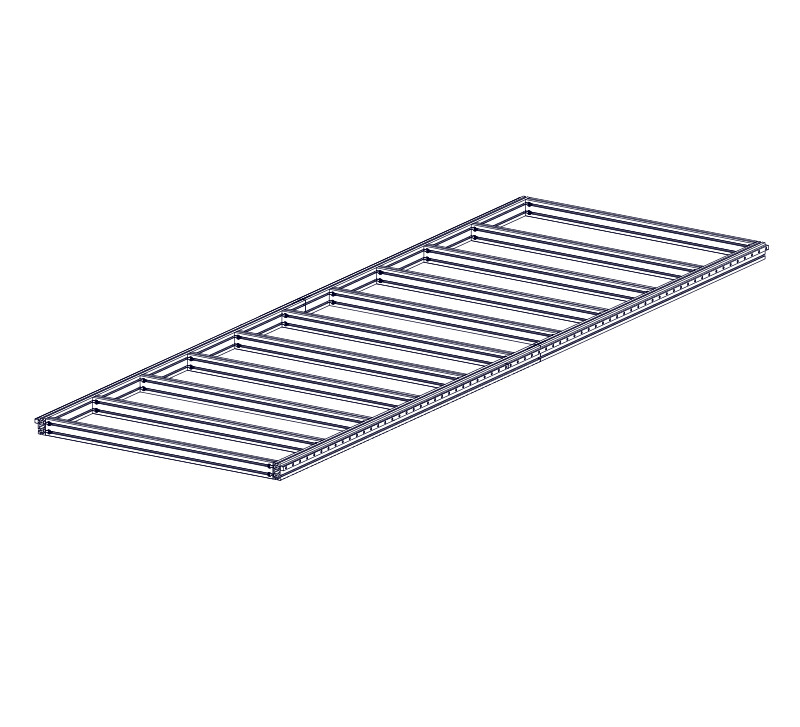
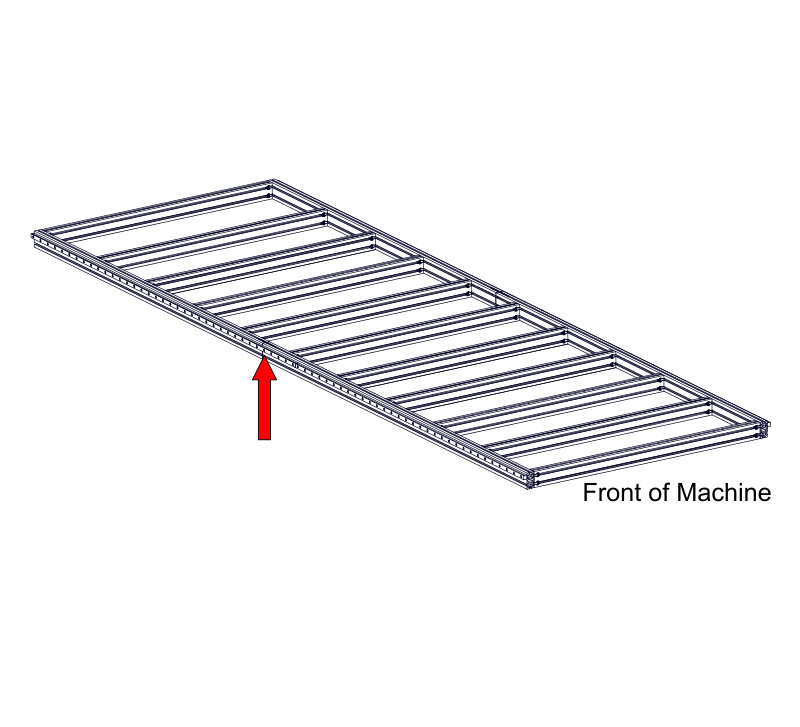
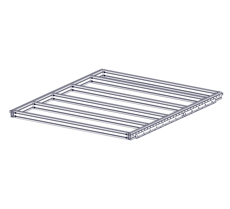
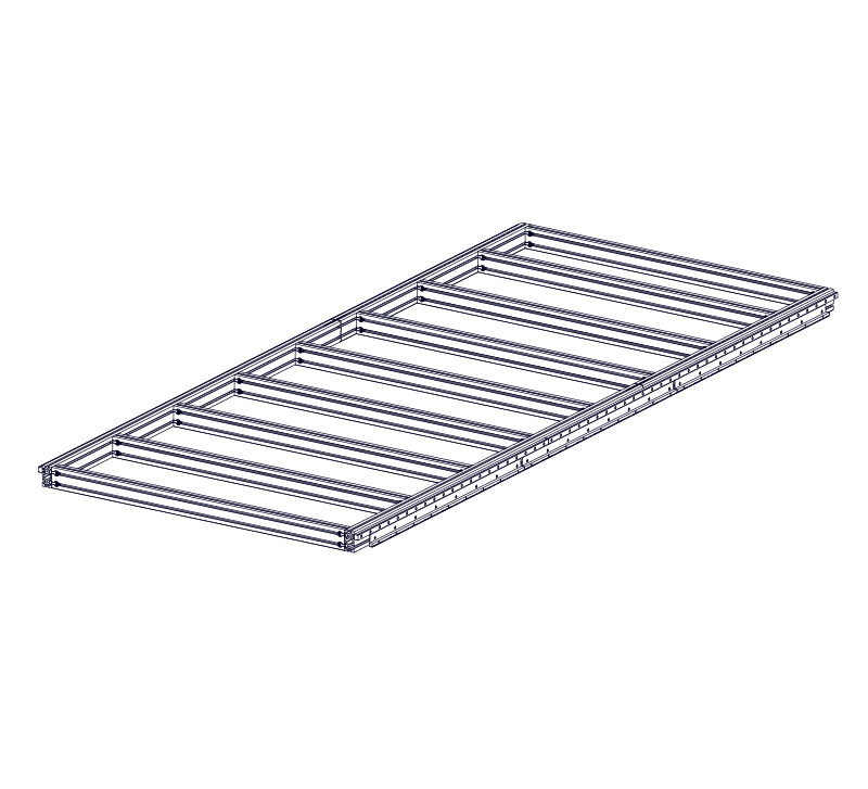
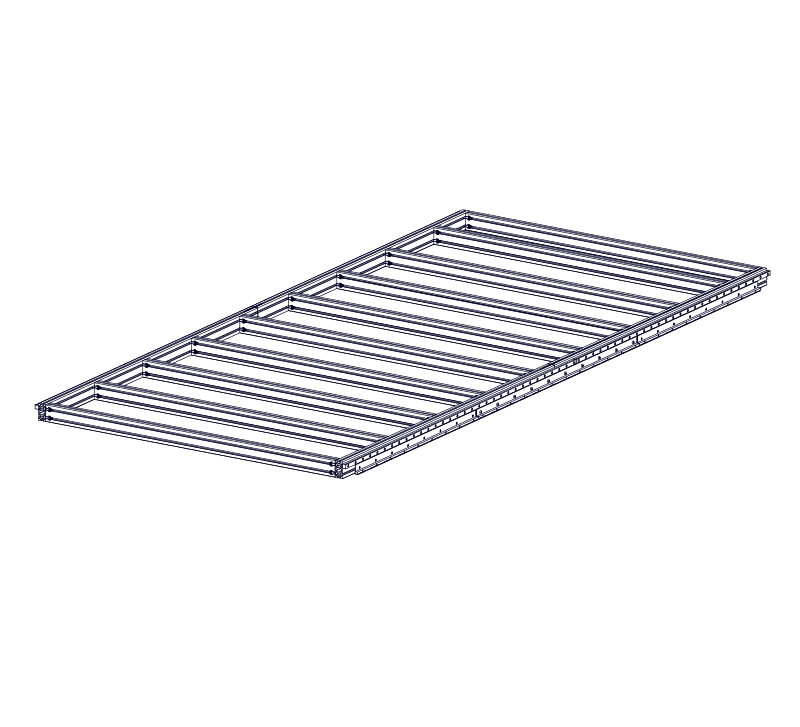
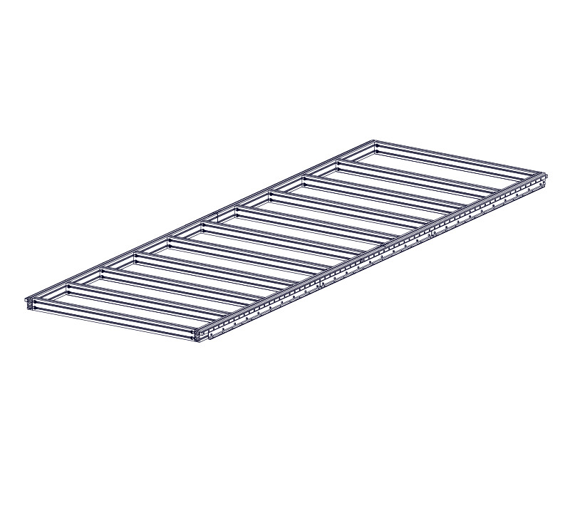
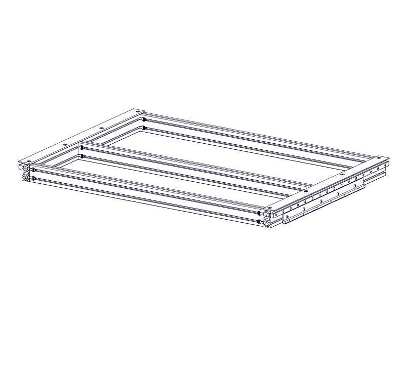
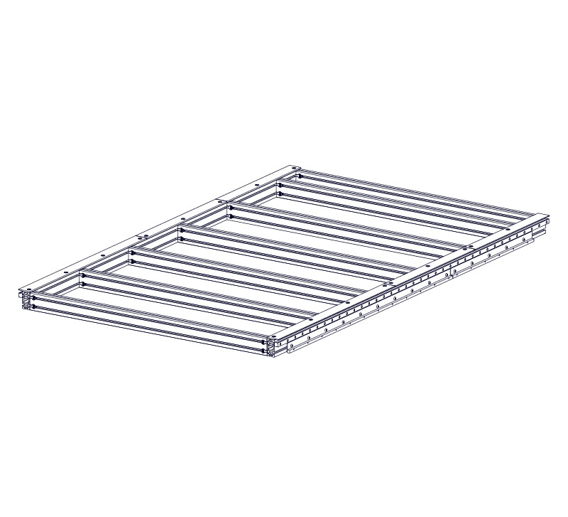
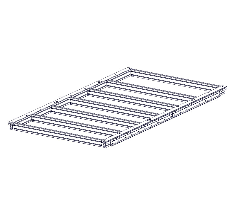
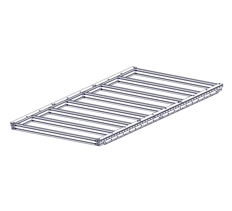
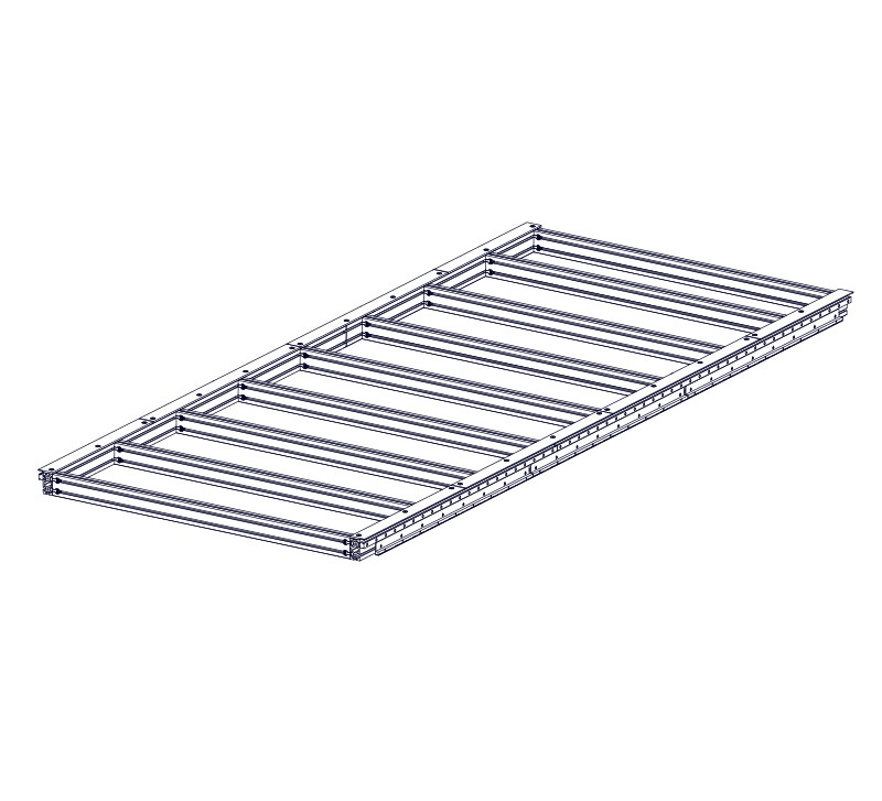
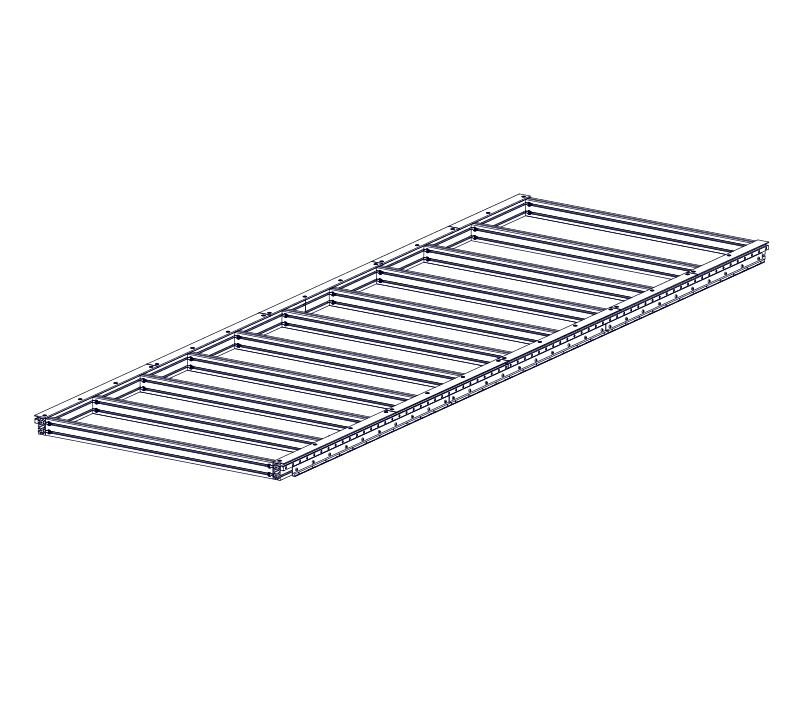
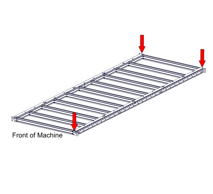
Images may not be representative of actual machine size, however assembly steps and parts lists are specific for the machine configuration selected.
Section Note
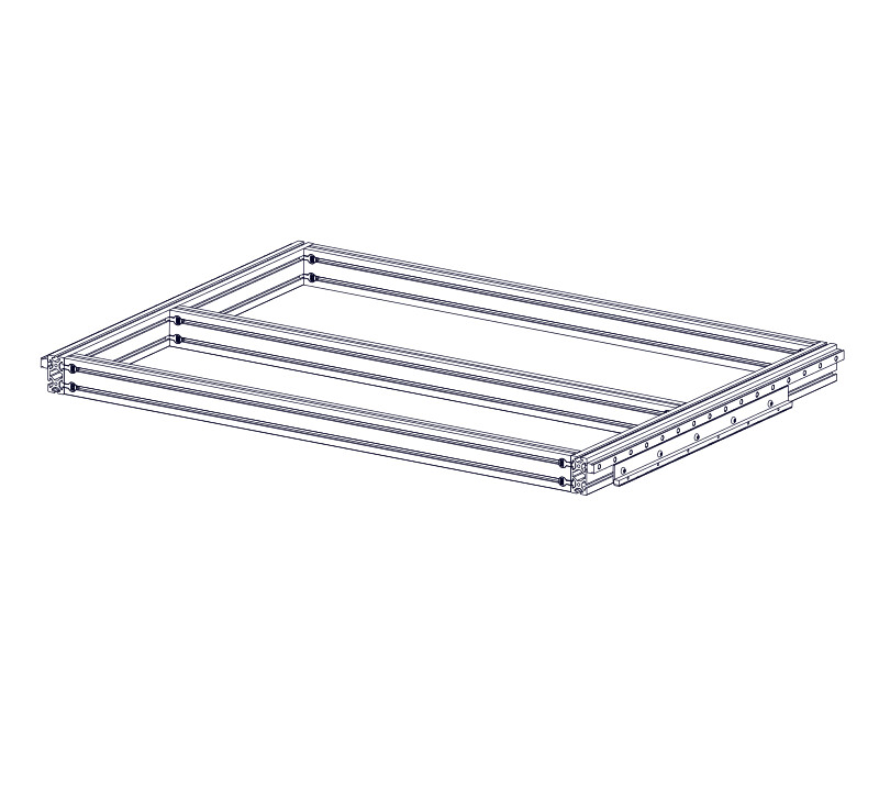
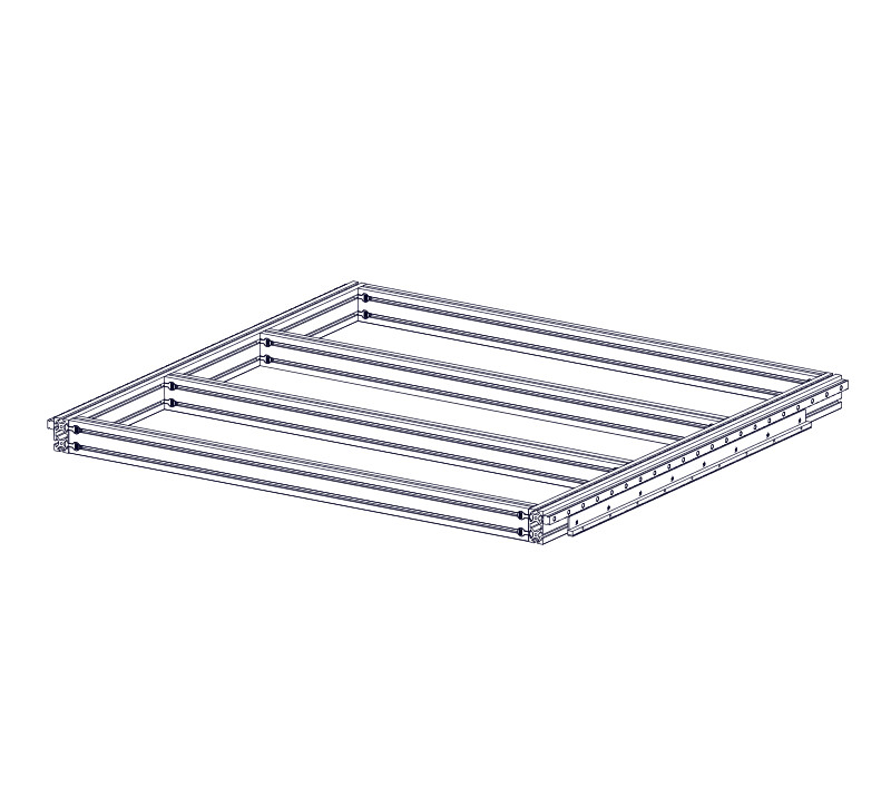
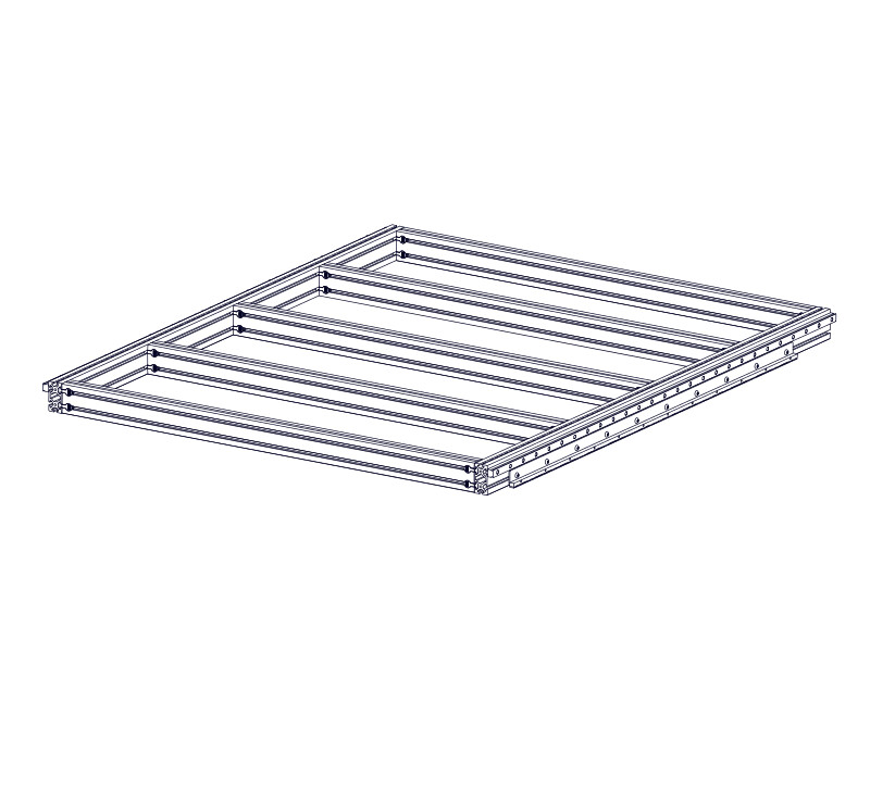
Remaining images are shown without Avid CNC leg kit.
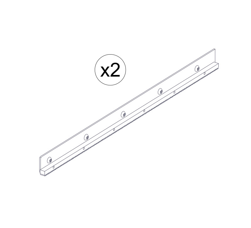
2.1 - Linear Rails

Parts List
| ID | QTY | Part/Description | Package Label |
|---|---|---|---|
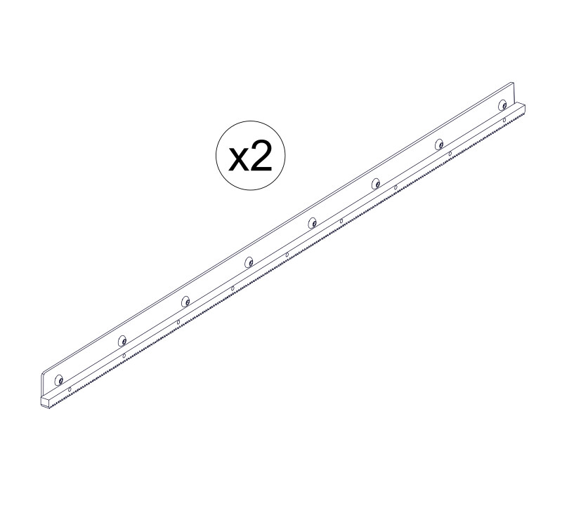
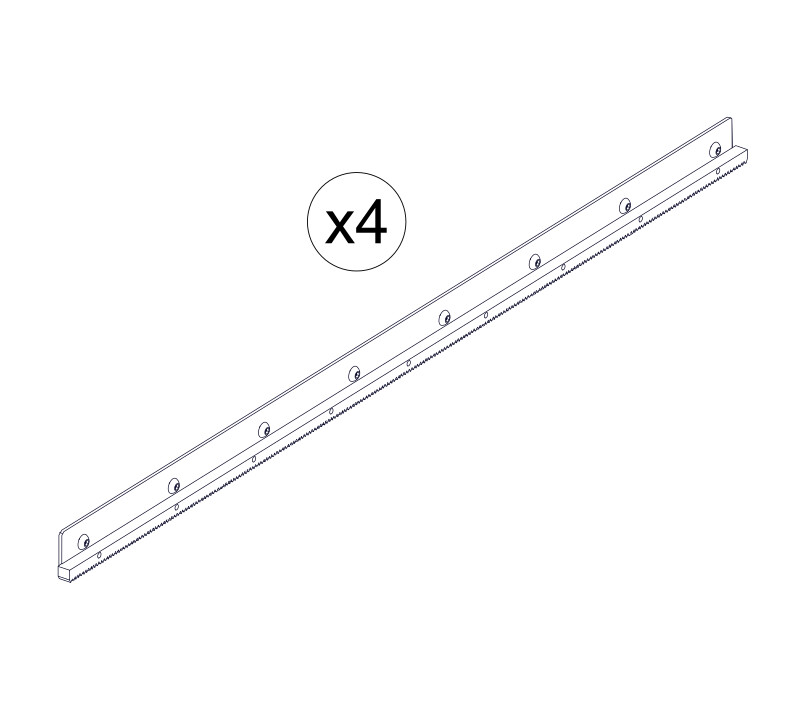
A | 2 4 | Linear Rail, 950mm (37-3/8") Linear Rail, 1000mm (39-3/8") Linear Rail, 1200mm (47-1/4") Linear Rail, 1250mm (49-1/4") Linear Rail, 1500mm (59-1/16") Linear Rail, 1600mm (63") Linear Rail, 1750mm (68-7/8") Linear Rail, 1800mm (70-7/8") Linear Rail, 1900mm (74-13/16") Linear Rail, 2000mm (78-3/4") Linear Rail, 2100mm (82-11/16") Linear Rail, 2200mm (86-5/8") Linear Rail, 2250mm (88-9/16") Linear Rail, 2500mm (98-7/16") Linear Rail, 2550mm (100-3/8") Linear Rail, 2600mm (102-3/8") Linear Rail, 2750mm (108-1/4") Linear Rail, 2800mm (110-1/4") Linear Rail, 2850mm (112-3/16") Linear Rail, 3000mm (118-1/8") Linear Rail, 3150mm (124") Linear Rail, 3300mm (129-15/16") Linear Rail, 3450mm (135-13/16") | Table Steel Kit |
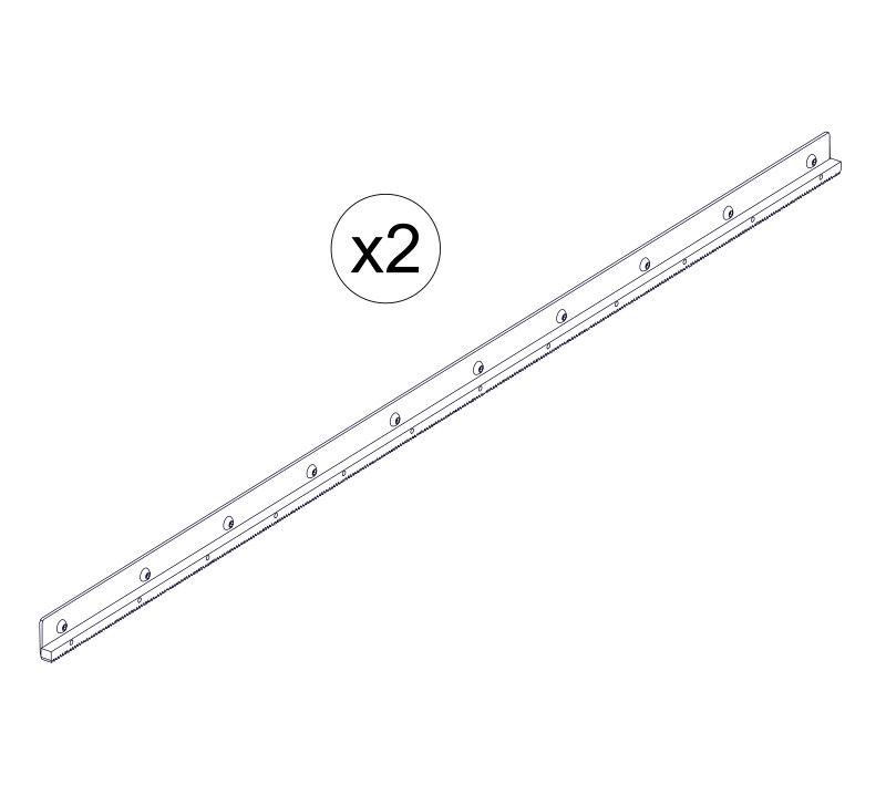
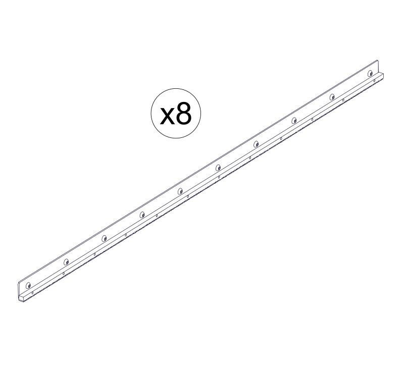
B | 2 2 4 4 6 | Linear Rail, 1600mm (63") Linear Rail, 1900mm (74-13/16") Linear Rail, 2200mm (86-5/8") Linear Rail, 2750mm (108-1/4") Linear Rail, 2850mm (112-3/16") Linear Rail, 2850mm (112-3/16") Linear Rail, 3500mm (137-13/16") Linear Rail, 3500mm (137-13/16") Linear Rail, 3500mm (137-13/16") Linear Rail, 3500mm (137-13/16") | Table Steel Kit |
C | 4 | Linear Rail, 3500mm (137-13/16") | Table Steel Kit |
1 | GH20-24-FAST GH20-36-FAST GH20-48-FAST GH20-60-FAST GH20-72-FAST GH20-84-FAST GH20-96-FAST GH20-108-FAST GH20-120-FAST GH20-132-FAST GH20-144-FAST GH20-156-FAST GH20-168-FAST GH20-180-FAST GH20-192-FAST GH20-204-FAST GH20-216-FAST GH20-228-FAST GH20-240-FAST GH20-252-FAST GH20-264-FAST GH20-276-FAST GH20-288-FAST GH20-300-FAST GH20-312-FAST GH20-324-FAST GH20-336-FAST GH20-348-FAST GH20-360-FAST GH20-372-FAST GH20-384-FAST GH20-396-FAST GH20-408-FAST GH20-420-FAST GH20-432-FAST GH20-444-FAST GH20-456-FAST GH20-468-FAST GH20-480-FAST | Base Hardware | |
D | M5 x 20mm Socket Head Cap Screw ( per bag) | GH20-24-FASTGH20-36-FASTGH20-48-FASTGH20-60-FASTGH20-72-FASTGH20-84-FASTGH20-96-FASTGH20-108-FASTGH20-120-FASTGH20-132-FASTGH20-144-FASTGH20-156-FASTGH20-168-FASTGH20-180-FASTGH20-192-FASTGH20-204-FASTGH20-216-FASTGH20-228-FASTGH20-240-FASTGH20-252-FASTGH20-264-FASTGH20-276-FASTGH20-288-FASTGH20-300-FASTGH20-312-FASTGH20-324-FASTGH20-336-FASTGH20-348-FASTGH20-360-FASTGH20-372-FASTGH20-384-FASTGH20-396-FASTGH20-408-FASTGH20-420-FASTGH20-432-FASTGH20-444-FASTGH20-456-FASTGH20-468-FASTGH20-480-FASTPackaged in | |
E | M5 Slide-in T-Nut ( per bag) | GH20-24-FASTGH20-36-FASTGH20-48-FASTGH20-60-FASTGH20-72-FASTGH20-84-FASTGH20-96-FASTGH20-108-FASTGH20-120-FASTGH20-132-FASTGH20-144-FASTGH20-156-FASTGH20-168-FASTGH20-180-FASTGH20-192-FASTGH20-204-FASTGH20-216-FASTGH20-228-FASTGH20-240-FASTGH20-252-FASTGH20-264-FASTGH20-276-FASTGH20-288-FASTGH20-300-FASTGH20-312-FASTGH20-324-FASTGH20-336-FASTGH20-348-FASTGH20-360-FASTGH20-372-FASTGH20-384-FASTGH20-396-FASTGH20-408-FASTGH20-420-FASTGH20-432-FASTGH20-444-FASTGH20-456-FASTGH20-468-FASTGH20-480-FASTPackaged in | |
1 | Linear Rail Setting Jig Kit GHH20-JIG-00 | Base Hardware | |
F | 2 | Rail Alignment Jig | GHH20-JIG-00Packaged in |
G | 4 | M8 x 25mm Socket Head Cap Screw | GHH20-JIG-00Packaged in |
H | 4 | M8 Roll-in T-Nut | GHH20-JIG-00Packaged in |
I | 4 | Linear Bearing Block GHH20CA | Gantry Hardware |
J | 4 | M6 Flush Grease Fitting | Gantry Hardware |
1 | LPRO-GREASE-KIT-19.1 | Base Hardware | |
K | 1 | Grease Gun | LPRO-GREASE-KIT-19.1Packaged in |
L | 1 | Tube of Grease | LPRO-GREASE-KIT-19.1Packaged in |
M | 1 | Needle Tip Adapter | LPRO-GREASE-KIT-19.1Packaged in |
Tools List
| Requirement | Tool |
|---|---|
| Required | 4mm Ball-End Allen Wrench |
| Required | 6mm Ball-End Allen Wrench |
| Required | Adjustable Wrench |
| Required | (2) Clamps |
| Required | Tape Measure |
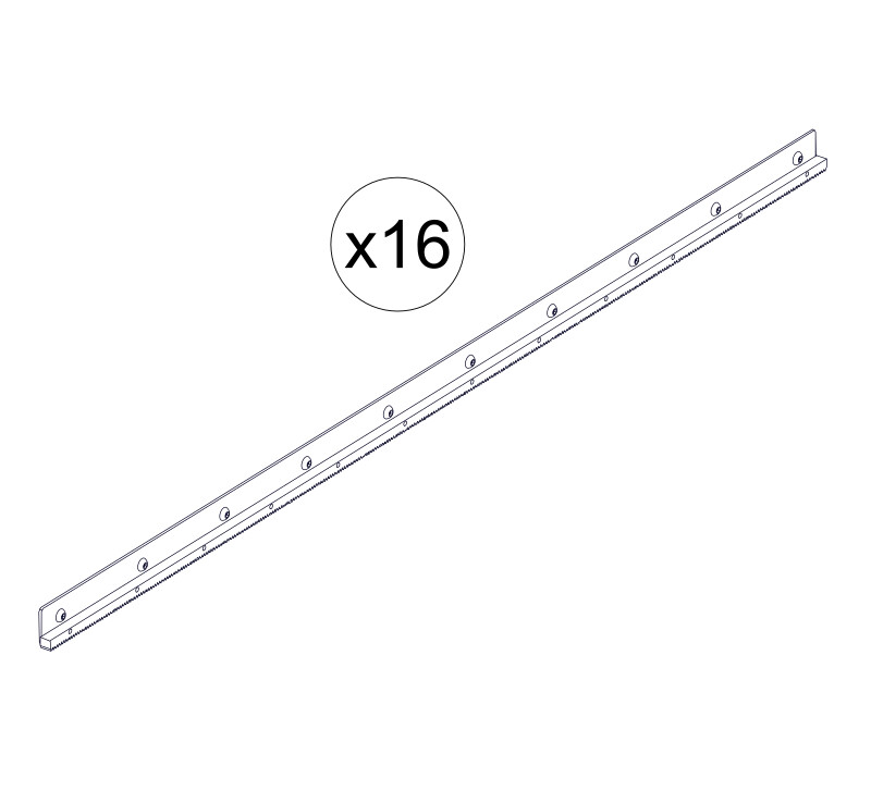
2.1.1 - Linear Rail Assembly
2.1.1.1
- Partially thread M5 x 20mm Socket Head Cap Screws D onto M5 Slide-in T-Nuts E , through the Linear Rail, 950mm (37-3/8") 1000mm (39-3/8") 1200mm (47-1/4") 1250mm (49-1/4") 1500mm (59-1/16") 1600mm (63") 1750mm (68-7/8") 1800mm (70-7/8") 1900mm (74-13/16") 2000mm (78-3/4") 2100mm (82-11/16") 2200mm (86-5/8") 2500mm (98-7/16") 2550mm (100-3/8") 2600mm (102-3/8") 2750mm (108-1/4") 2800mm (110-1/4") 2850mm (112-3/16") 3000mm (118-1/8") 3150mm (124") 3300mm (129-15/16") 3450mm (135-13/16") A .
2.1.1.2
- Use the procedure in the previous step to assemble the following linear rails:
- (2) Linear Rail, 950mm (37-3/8") A
- (2) Linear Rail, 1250mm (49-1/4") A
- (2) Linear Rail, 1600mm (63") A
- (2) Linear Rail, 1900mm (74-13/16") A
- (2) Linear Rail, 2200mm (86-5/8") A
- (4) Linear Rail, 2200mm (86-5/8") A
- (4) Linear Rail, 2850mm (112-3/16") A
- (2) Linear Rail, 950mm (37-3/8") A
- (2) Linear Rail, 1600mm (63") B
- (2) Linear Rail, 1250mm (49-1/4") A
- (2) Linear Rail, 1600mm (63") B
- (2) Linear Rail, 1250mm (49-1/4") A
- (2) Linear Rail, 1900mm (74-13/16") B
- (2) Linear Rail, 1600mm (63") A
- (2) Linear Rail, 1900mm (74-13/16") B
- (2) Linear Rail, 1600mm (63") A
- (2) Linear Rail, 2200mm (86-5/8") B
- (2) Linear Rail, 1900mm (74-13/16") A
- (2) Linear Rail, 2200mm (86-5/8") B
- (2) Linear Rail, 1900mm (74-13/16") A
- (2) Linear Rail, 2850mm (112-3/16") B
- (2) Linear Rail, 2200mm (86-5/8") A
- (2) Linear Rail, 2850mm (112-3/16") B
- (2) Linear Rail, 1900mm (74-13/16") A
- (2) Linear Rail, 3500mm (137-13/16") B
- (2) Linear Rail, 2500mm (98-7/16") A
- (2) Linear Rail, 3500mm (137-13/16") B
- (2) Linear Rail, 2750mm (108-1/4") A
- (2) Linear Rail, 3500mm (137-13/16") B
- (2) Linear Rail, 3000mm (118-1/8") A
- (2) Linear Rail, 3500mm (137-13/16") B
- (2) Linear Rail, 3300mm (129-15/16") A
- (2) Linear Rail, 3500mm (137-13/16") B
- (4) Linear Rail, 2200mm (86-5/8") A
- (2) Linear Rail, 2750mm (108-1/4") B
- (2) Linear Rail, 1750mm (68-7/8") A
- (4) Linear Rail, 2850mm (112-3/16") B
- (2) Linear Rail, 2000mm (78-3/4") A
- (4) Linear Rail, 2850mm (112-3/16") B
- (2) Linear Rail, 1000mm (39-3/8") A
- (4) Linear Rail, 3500mm (137-13/16") B
- (2) Linear Rail, 2600mm (102-3/8") A
- (4) Linear Rail, 2850mm (112-3/16") B
- (2) Linear Rail, 1600mm (63") A
- (4) Linear Rail, 3500mm (137-13/16") B
- (2) Linear Rail, 1900mm (74-13/16") A
- (4) Linear Rail, 3500mm (137-13/16") B
- (2) Linear Rail, 2250mm (88-9/16") A
- (4) Linear Rail, 3500mm (137-13/16") B
- (2) Linear Rail, 2550mm (100-3/8") A
- (4) Linear Rail, 3500mm (137-13/16") B
- (2) Linear Rail, 2850mm (112-3/16") A
- (4) Linear Rail, 3500mm (137-13/16") B
- (2) Linear Rail, 3150mm (124") A
- (4) Linear Rail, 3500mm (137-13/16") B
- (2) Linear Rail, 3450mm (135-13/16") A
- (4) Linear Rail, 3500mm (137-13/16") B
- (2) Linear Rail, 2200mm (86-5/8") A
- (6) Linear Rail, 2850mm (112-3/16") B
- (2) Linear Rail, 1200mm (47-1/4") A
- (2) Linear Rail, 2850mm (112-3/16") B
- (4) Linear Rail, 3500mm (137-13/16") C
- (2) Linear Rail, 2800mm (110-1/4") A
- (6) Linear Rail, 2850mm (112-3/16") B
- (2) Linear Rail, 1200mm (47-1/4") A
- (6) Linear Rail, 3500mm (137-13/16") B
- (2) Linear Rail, 1500mm (59-1/16") A
- (6) Linear Rail, 3500mm (137-13/16") B
- (2) Linear Rail, 1800mm (70-7/8") A
- (6) Linear Rail, 3500mm (137-13/16") B
- (2) Linear Rail, 2100mm (82-11/16") A
- (6) Linear Rail, 3500mm (137-13/16") B
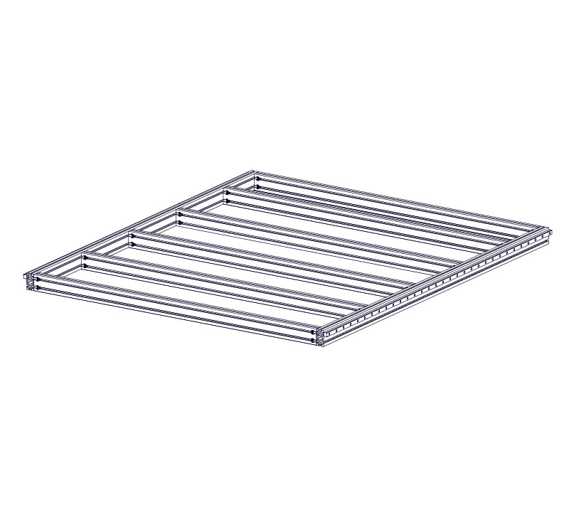
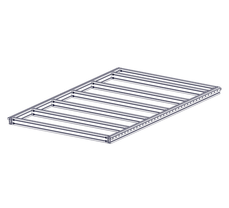
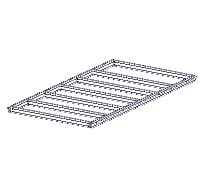
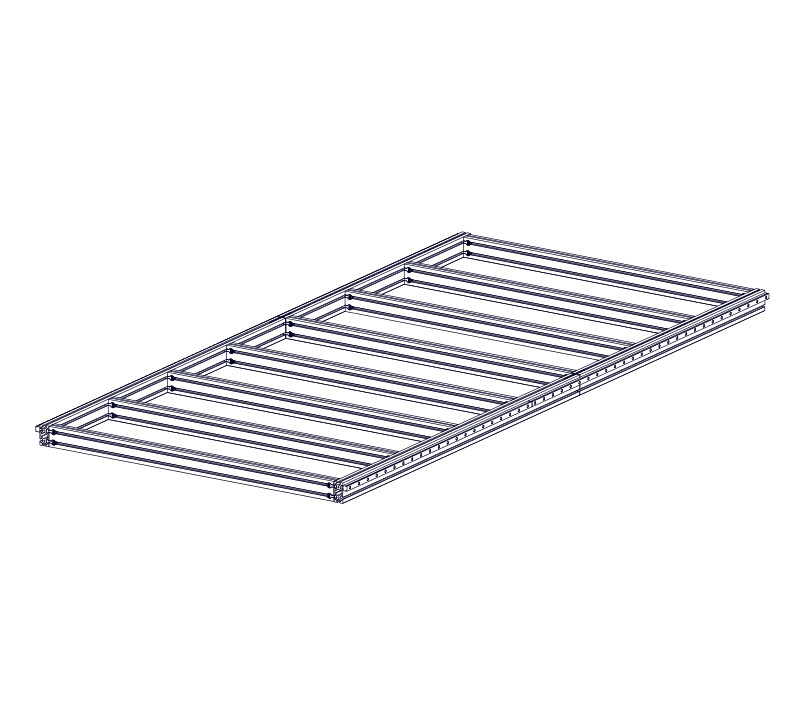
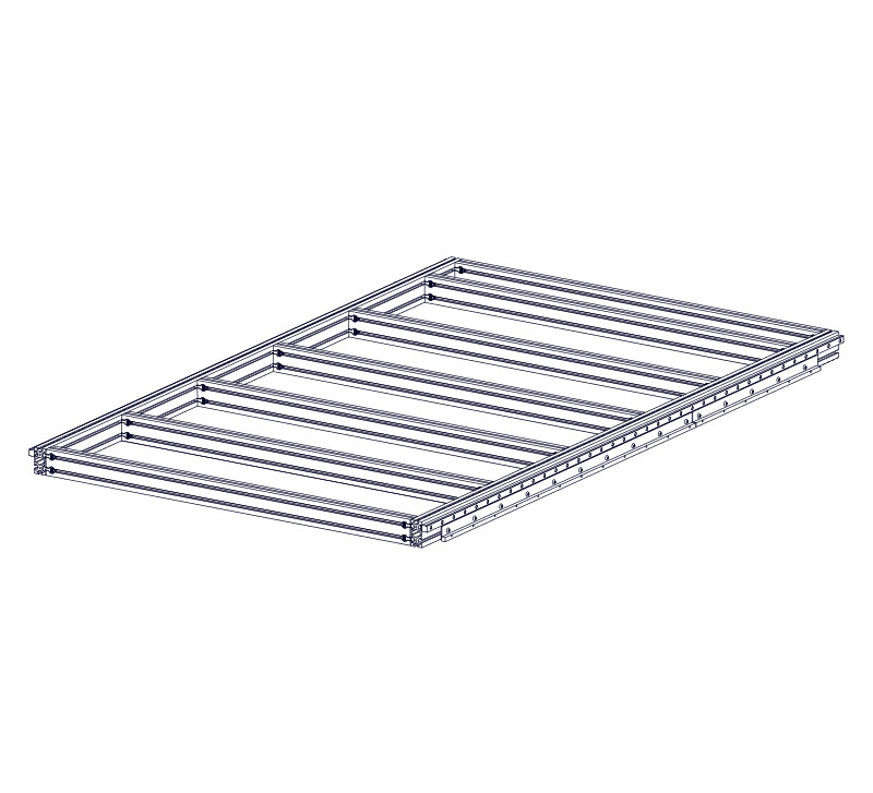
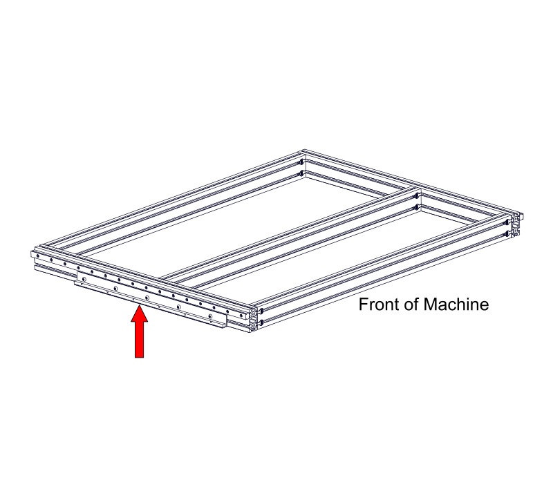
2.1.2 - Linear Rail Installation


2.1.2.2
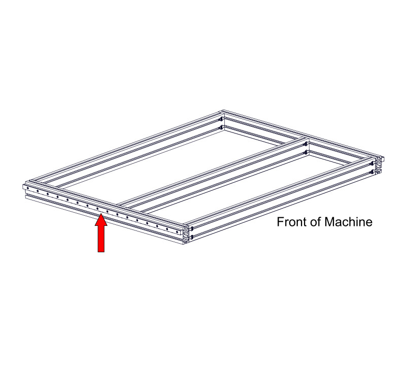
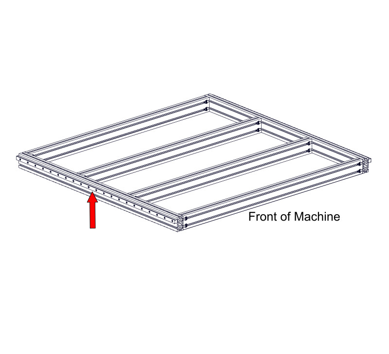
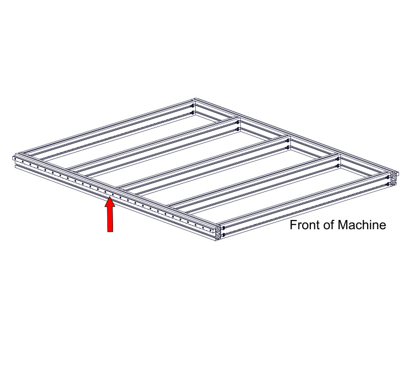
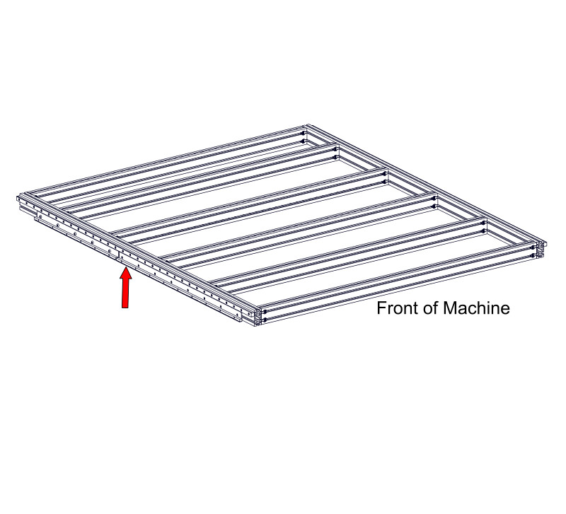
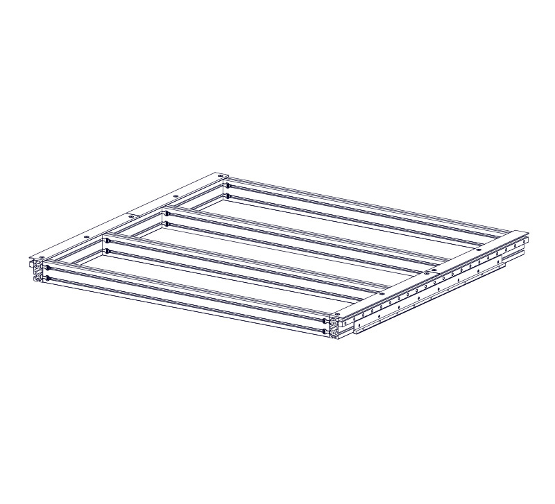
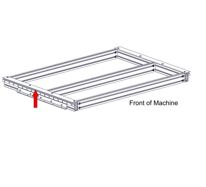
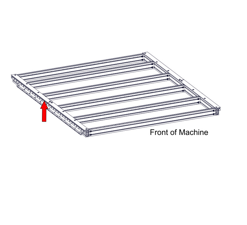
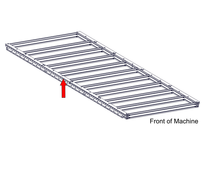
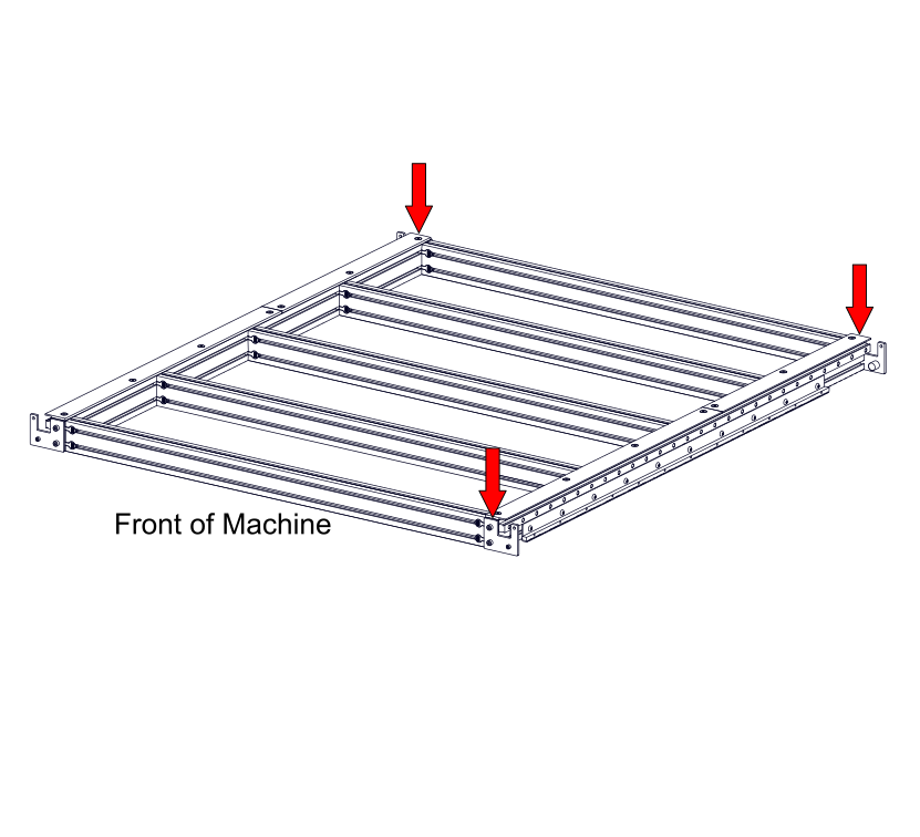
- From the front of the machine, slide an assembled Linear Rail, 950mm (37-3/8") A Linear Rail, 1900mm (74-13/16") B Linear Rail, 1750mm (68-7/8") A Linear Rail, 1900mm (74-13/16") A Linear Rail, 2200mm (86-5/8") A Linear Rail, 2500mm (98-7/16") A Linear Rail, 2750mm (108-1/4") A Linear Rail, 2850mm (112-3/16") A Linear Rail, 1600mm (63") B Linear Rail, 1900mm (74-13/16") B Linear Rail, 2200mm (86-5/8") B Linear Rail, 2850mm (112-3/16") B Linear Rail, 3500mm (137-13/16") B Linear Rail, 3500mm (137-13/16") B into the upper t-slot of the frame extrusion.
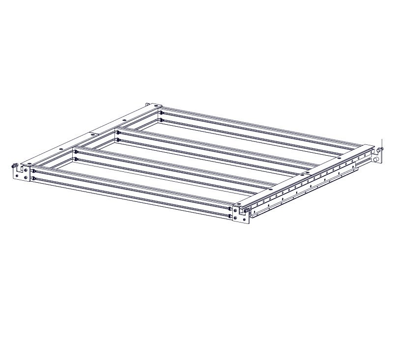
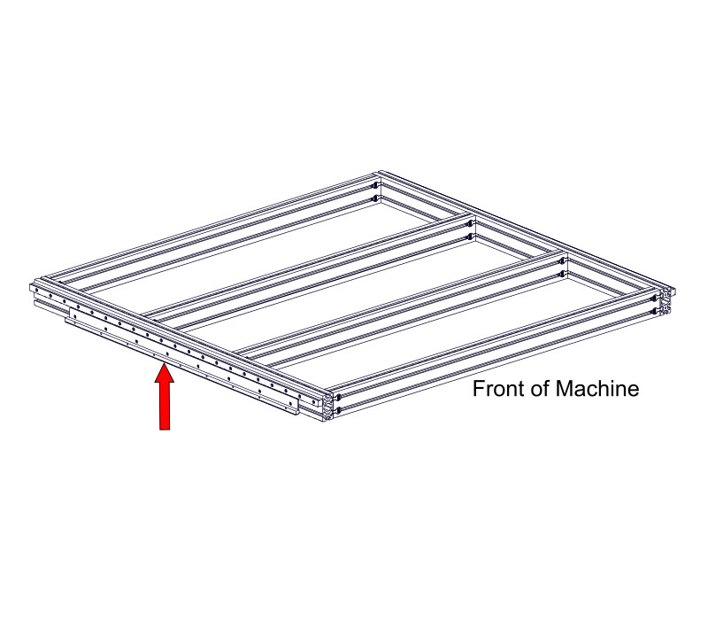
2.1.2.3
- From the front of the machine, slide an assembled Linear Rail, 1250mm (49-1/4") A Linear Rail, 1600mm (63") A Linear Rail, 1900mm (74-13/16") A Linear Rail, 2200mm (86-5/8") A Linear Rail, 1600mm (63") B Linear Rail, 1600mm (63") A Linear Rail, 2850mm (112-3/16") B into the upper t-slot of the frame extrusion.
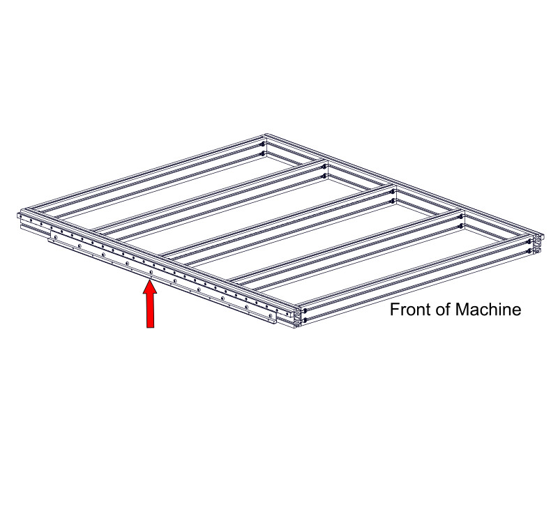
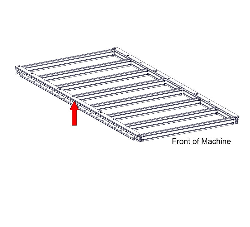
2.1.2.4
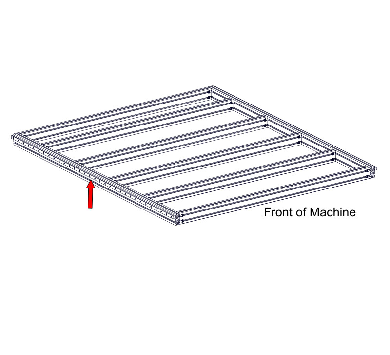
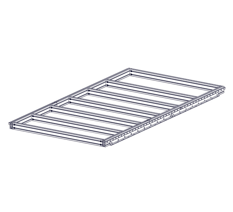
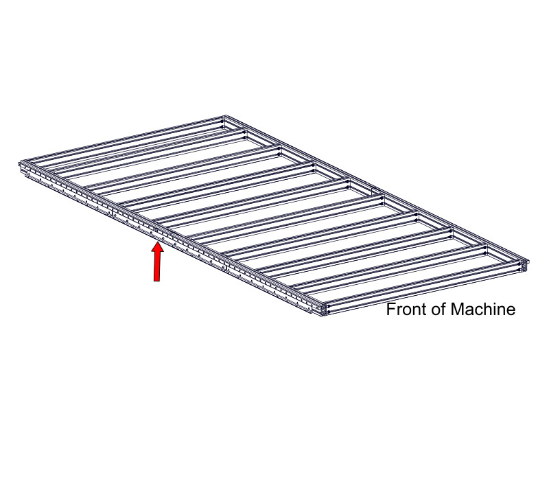
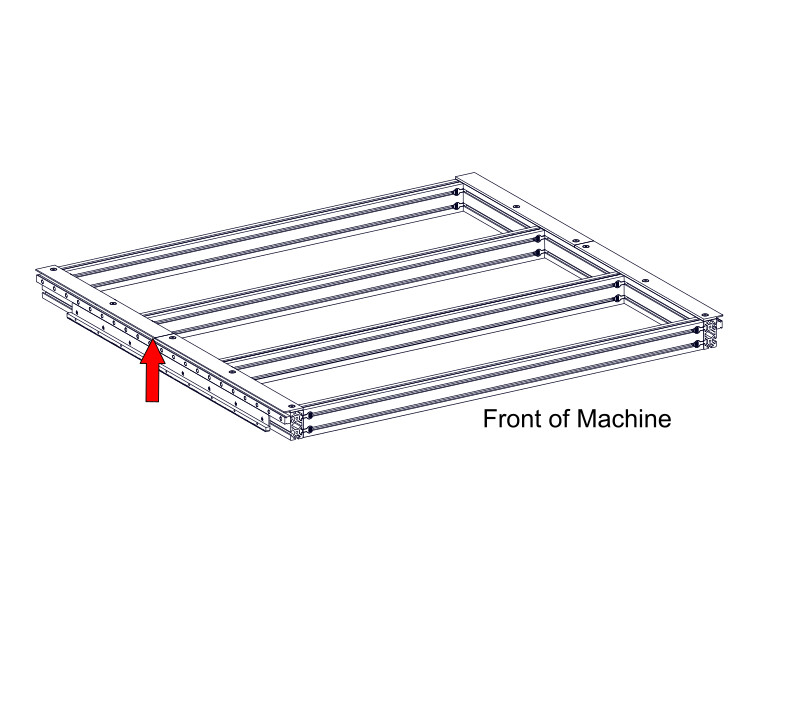
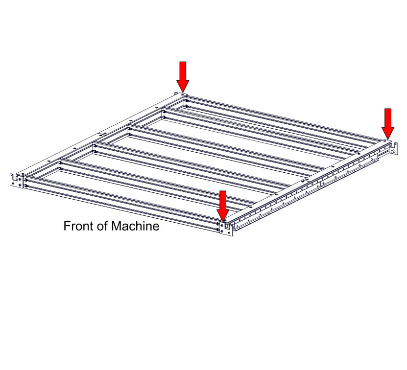
- From the front of the machine, slide an assembled Linear Rail, 2850mm (112-3/16") A Linear Rail, 3000mm (118-1/8") A Linear Rail, 3300mm (129-15/16") A Linear Rail, 3500mm (137-13/16") B into the upper t-slot of the frame extrusion.
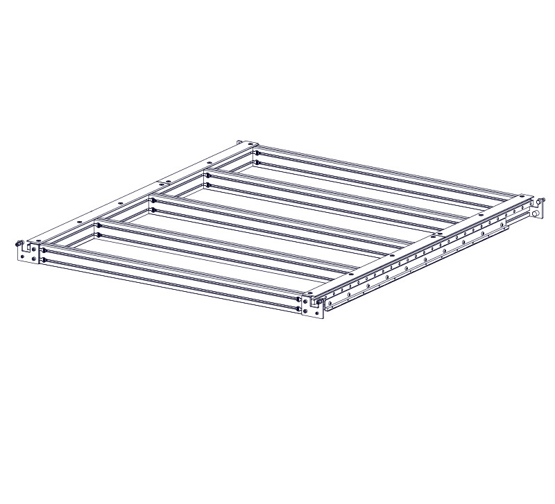
2.1.2.5
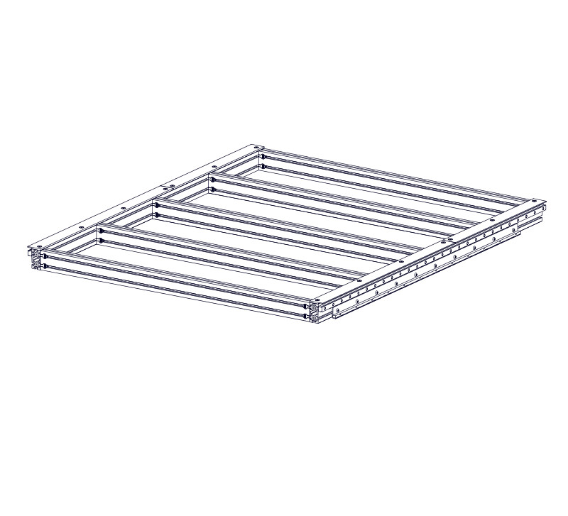
- From the front of the machine, slide an additional two assembled linear rails into the extrusion in the following order:
- (1) Linear Rail 2200mm (86-5/8") A
- (1) Linear Rail 2750mm (108-1/4") B
- (2) Linear Rail 2850mm (112-3/16") B
- (1) Linear Rail 2850mm (112-3/16") B
- (1) Linear Rail 2000mm (78-3/4") A
- (1) Linear Rail 3500mm (137-13/16") B
- (1) Linear Rail 1000mm (39-3/8") A
- (1) Linear Rail 2850mm (112-3/16") B
- (1) Linear Rail 2600mm (102-3/8") A
- (1) Linear Rail 3500mm (137-13/16") B
- (1) Linear Rail 1600mm (63") A
- (1) Linear Rail 3500mm (137-13/16") B
- (1) Linear Rail 1900mm (74-13/16") A
- (1) Linear Rail 3500mm (137-13/16") B
- (1) Linear Rail 2250mm (88-9/16") A
- (1) Linear Rail 3500mm (137-13/16") B
- (1) Linear Rail 2550mm (100-3/8") A
- (1) Linear Rail 3500mm (137-13/16") B
- (1) Linear Rail 2850mm (112-3/16") A
- (1) Linear Rail 3500mm (137-13/16") B
- (1) Linear Rail 3150mm (124") A
- (1) Linear Rail 3500mm (137-13/16") B
- (1) Linear Rail 3450mm (135-13/16") A
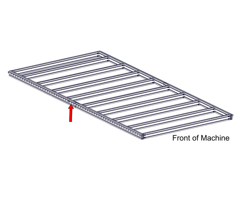
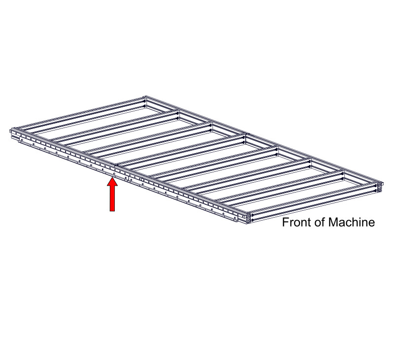
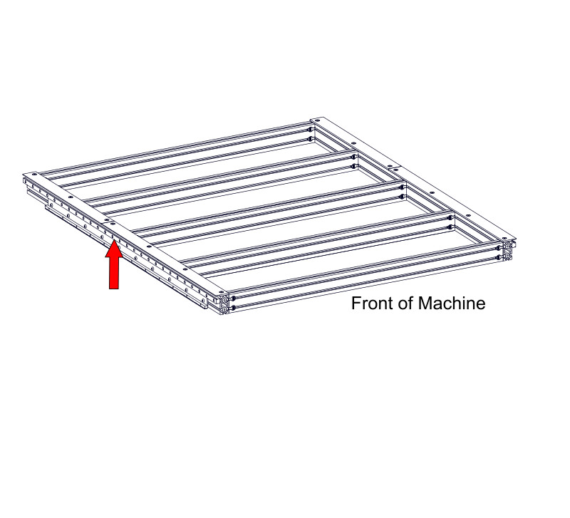
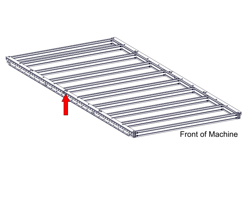
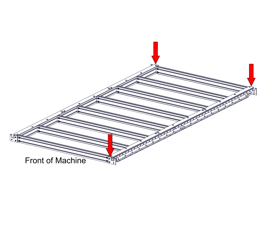
2.1.2.6
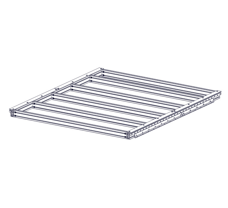
- From the front of the machine, slide an additional three assembled linear rails into the extrusion in the following order:
- (3) Linear Rail 2850mm (112-3/16") B
- (2) Linear Rail 3500mm (137-13/16") C
- (1) Linear Rail 1200mm (47-1/4") A
- (2) Linear Rail 2850mm (112-3/16") B
- (1) Linear Rail 2800mm (110-1/4") A
- (2) Linear Rail 3500mm (137-13/16") B
- (1) Linear Rail 1200mm (47-1/4") A
- (2) Linear Rail 3500mm (137-13/16") B
- (1) Linear Rail 1500mm (59-1/16") A
- (2) Linear Rail 3500mm (137-13/16") B
- (1) Linear Rail 1800mm (70-7/8") A
- (2) Linear Rail 3500mm (137-13/16") B
- (1) Linear Rail 2100mm (82-11/16") A
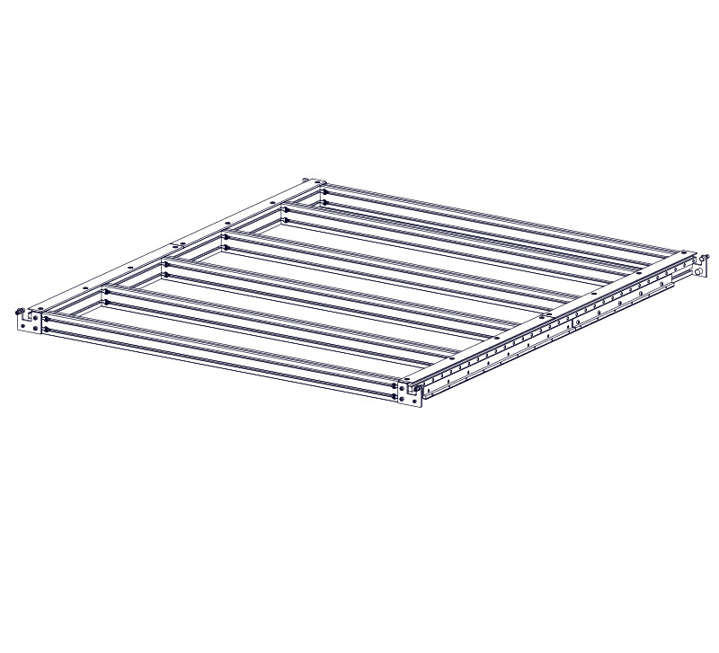
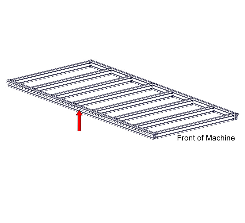
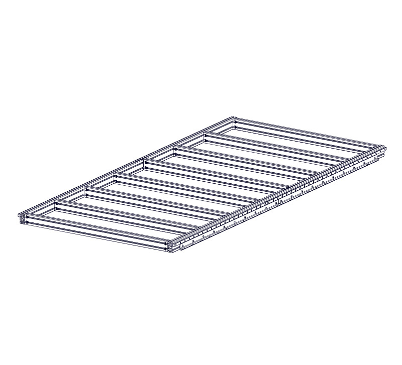
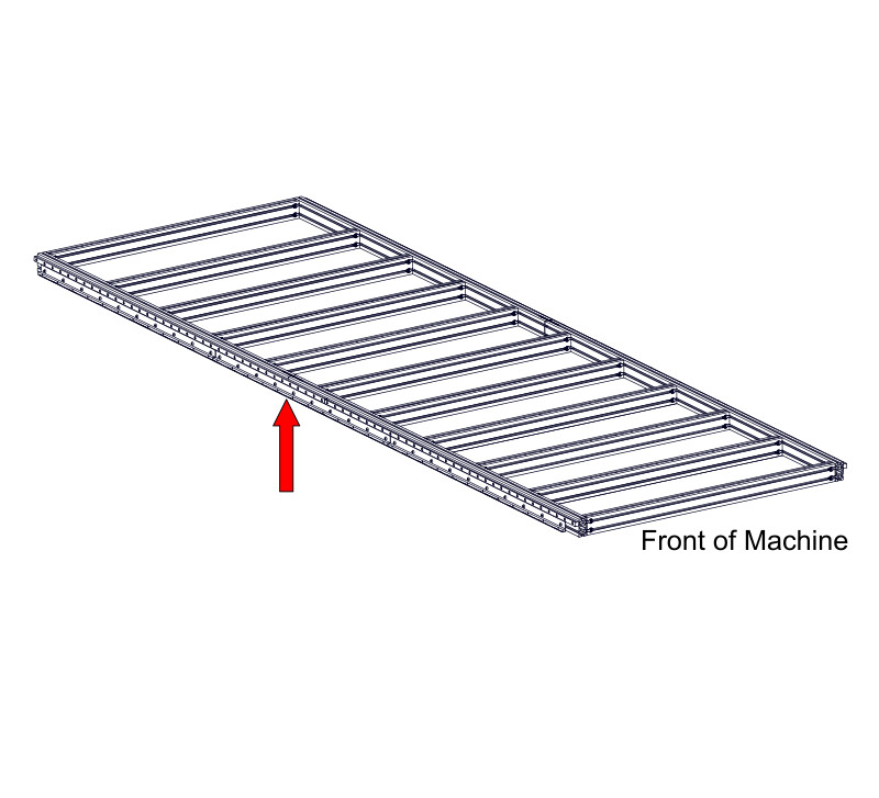
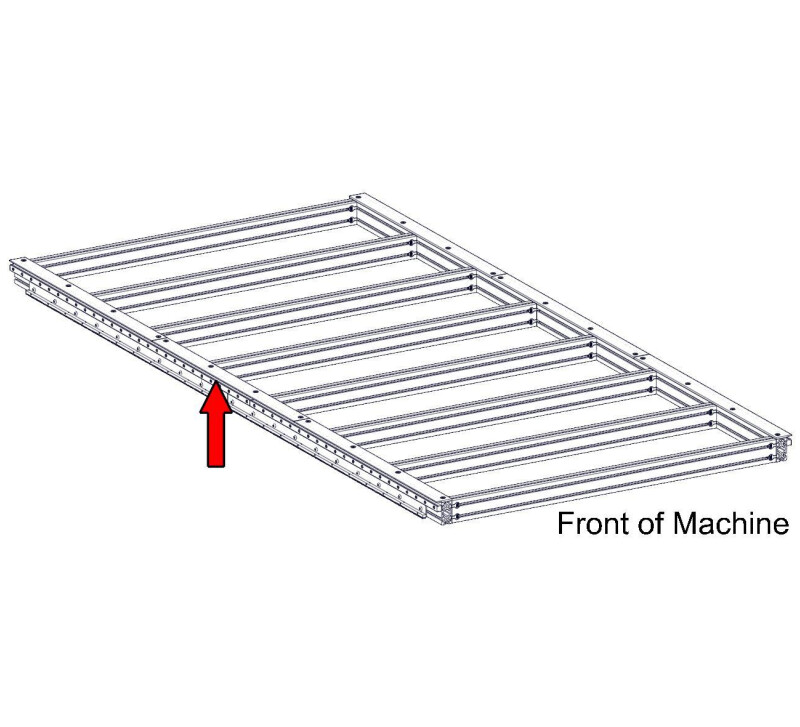
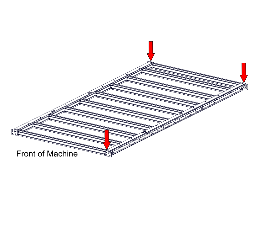
2.1.2.7

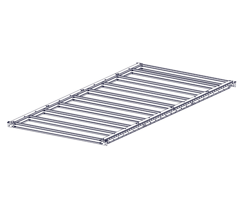
- The ends of the linear rails should be roughly flush with the ends of the frame extrusion.
2.1.2.8
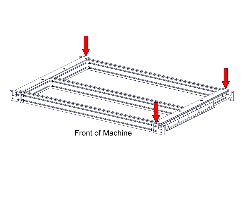
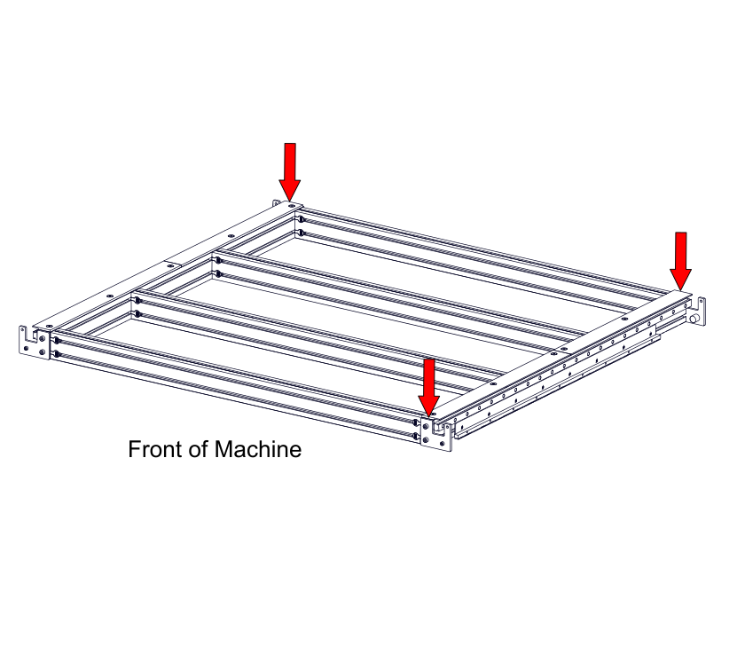
- Attach the Rail Alignment Jig F to the frame extrusion using M8 x 25mm Socket Head Cap Screws G and M8 Roll-in T-Nuts H .
- Fully tighten the fasteners.
2.1.2.9

- Clamp the end of the linear rail to the rail alignment jig.
2.1.2.10

- Repeat this process with the second rail alignment jig at the other end of the linear rail.
2.1.2.11


- With the linear rail clamped to the alignment jigs, fully tighten all linear rail fasteners.
- Remove the clamps and alignment jigs.
Info
The alignment jigs will be used again in the Gantry Assembly section.
2.1.2.12

- Repeat this process with the second rail alignment jig at the linear rail splice.
- Repeat this process with the second rail alignment jig at the linear rail splice.
- Repeat this process with the second rail alignment jig at the first linear rail splice.
- Repeat this process with the second rail alignment jig at the first linear rail splice.
2.1.2.13

- Fully tighten the linear rail fasteners on the clamped linear rail.
2.1.2.14

- Ensure the linear rails are flush at the splice and leave the alignment jig clamped at this location.
2.1.2.15
- Move the other alignment jig to the opposite end of the machine.
- Clamp the linear rail to the alignment jig.
2.1.2.16

- Fully tighten the linear rail fasteners on the clamped linear rail.
- Remove the clamps and alignment jigs.
2.1.2.17
- Move the other alignment jig to the next linear rail splice.
- Clamp the linear rail to the alignment jig.
2.1.2.18

- Fully tighten the linear rail fasteners on the clamped linear rail.
- Repeat the rail alignment procedure to clamp and tighten the fasteners on the remaining linear rails.
2.1.2.19
- Repeat the linear rail installation procedure on the other side of the machine.
Assembly Note
Linear rail hole covers are provided in your base hardware kit. We recommend that you install these covers after your machine is fully assembled and running.
2.1.3 - Linear Bearing Block Installation
2.1.3.1
- Identify the indicated reference edge on the Linear Bearing Block I .
Assembly Note
DO NOT remove the plastic bearing retainers until instructed to do so in a future step.
2.1.3.2
- Thread M6 Flush Grease Fittings J into the Linear Bearing Blocks I , noting the orientation of the reference edge.
- Hand tighten the grease fittings.
Assembly Note
You may need to relocate the pre-installed M6 button head cap screw to the other side of the linear bearing block.
2.1.3.3

- On each side of the machine, slide two linear bearing blocks onto the linear rails.
- Use the linear rail to push the plastic bearing retainer out of the linear bearing block, as shown.
Assembly Note
Ensure the linear bearing blocks are oriented correctly. Grease fittings face away from each other and reference edges face upwards.
2.1.4 - Linear Rail Alignment
2.1.4.1
- At the linear rail splice, loosen four fasteners on either side of the splice.
2.1.4.2
- Alternate tightening the loosened fasteners on either side of the splice, moving in towards the splice as you move the linear bearing block back and forth across the splice.
- Repeat this process at each linear rail splice location.
2.1.5 - Linear Bearing Block Greasing
2.1.5.1
- Assemble the Grease Gun K and Tube of Grease L , following the manufacturer's instructions.
- The video below shows how to assemble the grease gun.
2.1.5.2
- Loosen the end cap and install the Needle Tip Adapter M as shown.
Assembly Note
Be sure to tighten the end cap after installing the needle tip adapter.
2.1.5.3

- Ensure the grease gun is primed prior to use.
- Lubricate the linear bearing blocks with three pumps per block.
Maintenance Note
The blocks will need to be lubricated periodically. The required interval will depend upon machine use, loads, and ambient conditions. We suggest evaluating each month by cleaning the linear rails, moving the blocks along them, and checking for a lubricant film. If a film is not present, then add one additional pump of grease to your blocks.
2.2 - Gear Rack
Parts List
| ID | QTY | Part/Description | Package Label |
|---|---|---|---|
A | 2 | Gear Rack, 660mm (26") | Table Steel Kit |
A | 2 | Gear Rack, 660mm (26") | Table Steel Kit |
B | 2 | Gear Rack, 990mm (39") | Table Steel Kit |
B | 2 | Gear Rack, 990mm (39") | Table Steel Kit |
B | 4 6 | Gear Rack, 990mm (39") | Table Steel Kit |
C | 2 4 6 8 10 12 14 16 18 | Gear Rack, 1320mm (52") | Table Steel Kit |
2 | MGM-26-FAST-40 | Base Hardware | |
D | 10 | M8 x 12mm Button Head Cap Screw (5 per bag) | MGM-26-FAST-40Packaged in |
E | 10 | M8 Slide-in T-Nut (5 per bag) | MGM-26-FAST-40Packaged in |
MGM-39-FAST-40 | Base Hardware | ||
F | M8 x 12mm Button Head Cap Screw (8 per bag) | MGM-39-FAST-40Packaged in | |
G | M8 Slide-in T-Nut (8 per bag) | MGM-39-FAST-40Packaged in | |
MGM-52-FAST-40 | Base Hardware | ||
H | M8 x 12mm Button Head Cap Screw (10 per bag) | MGM-52-FAST-40Packaged in | |
I | M8 Slide-in T-Nut (10 per bag) | MGM-52-FAST-40Packaged in |
Tools List
| Requirement | Tool |
|---|---|
| Required | 5mm Ball-End Allen Wrench |
| Required | Tape Measure |
| Required | (2) Clamps |
2.2.1 - Gear Rack Assembly
2.2.1.1
- Partially thread M8 x 12mm Button Head Cap Screws D onto M8 Slide-in T-Nuts E , through the Gear Rack, 660mm (26") A .
- Partially thread M8 x 12mm Button Head Cap Screws D onto M8 Slide-in T-Nuts E , through the Gear Rack, 660mm (26") A .
- Partially thread M8 x 12mm Button Head Cap Screws F onto M8 Slide-in T-Nuts G , through the Gear Rack, 990mm (39") B .
- Partially thread M8 x 12mm Button Head Cap Screws F onto M8 Slide-in T-Nuts G , through the Gear Rack, 990mm (39") B .
- Partially thread M8 x 12mm Button Head Cap Screws H onto M8 Slide-in T-Nuts I , through the Gear Rack, 1320mm (52") C .
2.2.1.2


- Use the procedure in the previous step to assemble the following gear rack sections:
- (2) Gear Rack, 660mm (26") A
- (2) Gear Rack, 990mm (39") B
- (2) Gear Rack, 1320mm (52") C
- (2) Gear Rack, 660mm (26") A
- (2) Gear Rack, 990mm (39") B
- (2) Gear Rack, 660mm (26") A
- (2) Gear Rack, 1320mm (52") C
- (2) Gear Rack, 990mm (39") B
- (2) Gear Rack, 1320mm (52") C
- (4) Gear Rack, 1320mm (52") C
- (6) Gear Rack, 990mm (39") B
- (4) Gear Rack, 990mm (39") B
- (2) Gear Rack, 1320mm (52") C
- (2) Gear Rack, 990mm (39") B
- (4) Gear Rack, 1320mm (52") C
- (6) Gear Rack, 1320mm (52") C
- (6) Gear Rack, 990mm (39") B
- (2) Gear Rack, 1320mm (52") C
- (2) Gear Rack, 660mm (26") A
- (6) Gear Rack, 1320mm (52") C
- (2) Gear Rack, 990mm (39") B
- (6) Gear Rack, 1320mm (52") C
- (8) Gear Rack, 1320mm (52") C
- (2) Gear Rack, 660mm (26") A
- (2) Gear Rack, 990mm (39") B
- (6) Gear Rack, 1320mm (52") C
- (2) Gear Rack, 660mm (26") A
- (8) Gear Rack, 1320mm (52") C
- (2) Gear Rack, 660mm (26") A
- (8) Gear Rack, 1320mm (52") C
- (2) Gear Rack, 990mm (39") B
- (8) Gear Rack, 1320mm (52") C
- (10) Gear Rack, 1320mm (52") C
- (2) Gear Rack, 660mm (26") A
- (2) Gear Rack, 990mm (39") B
- (8) Gear Rack, 1320mm (52") C
- (2) Gear Rack, 660mm (26") A
- (10) Gear Rack, 1320mm (52") C
- (2) Gear Rack, 990mm (39") B
- (10) Gear Rack, 1320mm (52") C
- (12) Gear Rack, 1320mm (52") C
- (2) Gear Rack, 660mm (26") A
- (2) Gear Rack, 990mm (39") B
- (10) Gear Rack, 1320mm (52") C
- (4) Gear Rack, 990mm (39") B
- (10) Gear Rack, 1320mm (52") C
- (2) Gear Rack, 990mm (39") B
- (12) Gear Rack, 1320mm (52") C
- (2) Gear Rack, 660mm (26") A
- (4) Gear Rack, 990mm (39") B
- (10) Gear Rack, 1320mm (52") C
- (14) Gear Rack, 1320mm (52") C
- (2) Gear Rack, 660mm (26") A
- (2) Gear Rack, 990mm (39") B
- (12) Gear Rack, 1320mm (52") C
- (2) Gear Rack, 660mm (26") A
- (14) Gear Rack, 1320mm (52") C
- (2) Gear Rack, 990mm (39") B
- (14) Gear Rack, 1320mm (52") C
- (16) Gear Rack, 1320mm (52") C
- (2) Gear Rack, 660mm (26") A
- (2) Gear Rack, 990mm (39") B
- (14) Gear Rack, 1320mm (52") C
- (2) Gear Rack, 660mm (26") A
- (16) Gear Rack, 1320mm (52") C
- (2) Gear Rack, 990mm (39") B
- (16) Gear Rack, 1320mm (52") C
- (18) Gear Rack, 1320mm (52") C
- (2) Gear Rack, 660mm (26") A
- (2) Gear Rack, 990mm (39") B
- (16) Gear Rack, 1320mm (52") C
- (4) Gear Rack, 990mm (39") B
- (16) Gear Rack, 1320mm (52") C
2.2.2 - Gear Rack Installation
2.2.2.1
- Slide an assembled Gear Rack, 660mm (26") A Gear Rack, 990mm (39") B Gear Rack, 1320mm (52") C into the lower t-slot of the frame extrusion.
- Slide the following assembled gear rack sections into the lower t-slot of the frame extrusion:
- (1) Gear Rack, 660mm (26") A
- (1) Gear Rack, 990mm (39") B
- (1) Gear Rack, 660mm (26") A
- (1) Gear Rack, 1320mm (52") C
- (1) Gear Rack, 990mm (39") B
- (1) Gear Rack, 1320mm (52") C
- (2) Gear Rack, 1320mm (52") C
- (3) Gear Rack, 990mm (39") B
- (2) Gear Rack, 990mm (39") B
- (1) Gear Rack, 1320mm (52") C
- (1) Gear Rack, 990mm (39") B
- (2) Gear Rack, 1320mm (52") C
- (3) Gear Rack, 1320mm (52") C
- (3) Gear Rack, 990mm (39") B
- (1) Gear Rack, 1320mm (52") C
- (1) Gear Rack, 660mm (26") A
- (3) Gear Rack, 1320mm (52") C
- (1) Gear Rack, 990mm (39") B
- (3) Gear Rack, 1320mm (52") C
- (4) Gear Rack, 1320mm (52") C
- (1) Gear Rack, 660mm (26") A
- (1) Gear Rack, 990mm (39") B
- (3) Gear Rack, 1320mm (52") C
- (1) Gear Rack, 660mm (26") A
- (4) Gear Rack, 1320mm (52") C
- (1) Gear Rack, 660mm (26") A
- (4) Gear Rack, 1320mm (52") C
- (1) Gear Rack, 990mm (39") B
- (4) Gear Rack, 1320mm (52") C
- (5) Gear Rack, 1320mm (52") C
- (1) Gear Rack, 660mm (26") A
- (1) Gear Rack, 990mm (39") B
- (4) Gear Rack, 1320mm (52") C
- (1) Gear Rack, 660mm (26") A
- (5) Gear Rack, 1320mm (52") C
- (1) Gear Rack, 990mm (39") B
- (5) Gear Rack, 1320mm (52") C
- (6) Gear Rack, 1320mm (52") C
- (1) Gear Rack, 660mm (26") A
- (1) Gear Rack, 990mm (39") B
- (5) Gear Rack, 1320mm (52") C
- (2) Gear Rack, 990mm (39") B
- (5) Gear Rack, 1320mm (52") C
- (1) Gear Rack, 990mm (39") B
- (6) Gear Rack, 1320mm (52") C
- (1) Gear Rack, 660mm (26") A
- (2) Gear Rack, 990mm (39") B
- (5) Gear Rack, 1320mm (52") C
- (7) Gear Rack, 1320mm (52") C
- (1) Gear Rack, 660mm (26") A
- (1) Gear Rack, 990mm (39") B
- (6) Gear Rack, 1320mm (52") C
- (1) Gear Rack, 660mm (26") A
- (7) Gear Rack, 1320mm (52") C
- (1) Gear Rack, 990mm (39") B
- (7) Gear Rack, 1320mm (52") C
- (8) Gear Rack, 1320mm (52") C
- (1) Gear Rack, 660mm (26") A
- (1) Gear Rack, 990mm (39") B
- (7) Gear Rack, 1320mm (52") C
- (1) Gear Rack, 660mm (26") A
- (8) Gear Rack, 1320mm (52") C
- (1) Gear Rack, 990mm (39") B
- (8) Gear Rack, 1320mm (52") C
- (9) Gear Rack, 1320mm (52") C
- (1) Gear Rack, 660mm (26") A
- (1) Gear Rack, 990mm (39") B
- (8) Gear Rack, 1320mm (52") C
- (2) Gear Rack, 990mm (39") B
- (8) Gear Rack, 1320mm (52") C
2.2.2.2


- Position the gear rack 102mm (4") from the front of the machine.
- Position the gear rack flush with the end of the frame extrusion at the front of the machine.
- Tighten the gear rack fasteners.
- Tighten the gear rack fasteners ONLY on the first gear rack section.
Assembly Note
Gear rack may not sit flat against extrusion until fasteners are fully tightened. This will not impact function of the gear rack.
2.2.2.3

- Clamp an additional section of gear rack to the two sections to align the gear rack teeth.
- Clamp an additional section of gear rack to the first two sections to align the gear rack teeth.
Assembly Note
The gear rack for the gantry can be used for this purpose.
2.2.2.4

- Start at the splice location and tighten the fasteners, working towards the opposite end of the gear rack.
- Remove the clamps.
2.2.2.6
- Repeat the gear rack installation procedure on the other side of the machine.
2.3 - Linear Rail Dust Covers

Parts List
| ID | QTY | Part/Description | Package Label |
|---|---|---|---|
A | 2 4 6 8 10 12 14 16 18 20 22 24 | Linear Rail Dust Cover, 950mm (37-3/8") | Dust Cover Kit |
B | 2 2 2 4 6 8 10 12 | Linear Rail Dust Cover, 650mm (25-5/8") | Dust Cover Kit |
C | 2 | Linear Rail Dust Cover, 600mm (23-5/8") | Dust Cover Kit |
C | 2 6 8 10 | Linear Rail Dust Cover, 600mm (23-5/8") | Dust Cover Kit |
C | 2 4 | Linear Rail Dust Cover, 600mm (23-5/8") | Dust Cover Kit |
1 | CRP814-00-24-FAST CRP814-00-36-FAST CRP814-00-48-FAST CRP814-00-60-FAST CRP814-00-72-FAST CRP814-00-84-FAST CRP814-00-96-FAST CRP814-00-108-FAST CRP814-00-120-FAST CRP814-00-132-FAST CRP814-00-144-FAST CRP814-00-156-FAST CRP814-00-168-FAST CRP814-00-180-FAST CRP814-00-192-FAST CRP814-00-204-FAST CRP814-00-216-FAST CRP814-00-228-FAST CRP814-00-240-FAST CRP814-00-252-FAST CRP814-00-264-FAST CRP814-00-276-FAST CRP814-00-288-FAST CRP814-00-300-FAST CRP814-00-312-FAST CRP814-00-324-FAST CRP814-00-336-FAST CRP814-00-348-FAST CRP814-00-360-FAST CRP814-00-372-FAST CRP814-00-384-FAST CRP814-00-396-FAST CRP814-00-408-FAST CRP814-00-420-FAST CRP814-00-432-FAST CRP814-00-444-FAST CRP814-00-456-FAST CRP814-00-468-FAST CRP814-00-480-FAST | Dust Cover Kit | |
D | M8 x 16mm Flat Head Screw | CRP814-00-24-FASTCRP814-00-36-FASTCRP814-00-48-FASTCRP814-00-60-FASTCRP814-00-72-FASTCRP814-00-84-FASTCRP814-00-96-FASTCRP814-00-108-FASTCRP814-00-120-FASTCRP814-00-132-FASTCRP814-00-144-FASTCRP814-00-156-FASTCRP814-00-168-FASTCRP814-00-180-FASTCRP814-00-192-FASTCRP814-00-204-FASTCRP814-00-216-FASTCRP814-00-228-FASTCRP814-00-240-FASTCRP814-00-252-FASTCRP814-00-264-FASTCRP814-00-276-FASTCRP814-00-288-FASTCRP814-00-300-FASTCRP814-00-312-FASTCRP814-00-324-FASTCRP814-00-336-FASTCRP814-00-348-FASTCRP814-00-360-FASTCRP814-00-372-FASTCRP814-00-384-FASTCRP814-00-396-FASTCRP814-00-408-FASTCRP814-00-420-FASTCRP814-00-432-FASTCRP814-00-444-FASTCRP814-00-456-FASTCRP814-00-468-FASTCRP814-00-480-FASTPackaged in | |
E | M8 Roll-in T-Nut | CRP814-00-24-FASTCRP814-00-36-FASTCRP814-00-48-FASTCRP814-00-60-FASTCRP814-00-72-FASTCRP814-00-84-FASTCRP814-00-96-FASTCRP814-00-108-FASTCRP814-00-120-FASTCRP814-00-132-FASTCRP814-00-144-FASTCRP814-00-156-FASTCRP814-00-168-FASTCRP814-00-180-FASTCRP814-00-192-FASTCRP814-00-204-FASTCRP814-00-216-FASTCRP814-00-228-FASTCRP814-00-240-FASTCRP814-00-252-FASTCRP814-00-264-FASTCRP814-00-276-FASTCRP814-00-288-FASTCRP814-00-300-FASTCRP814-00-312-FASTCRP814-00-324-FASTCRP814-00-336-FASTCRP814-00-348-FASTCRP814-00-360-FASTCRP814-00-372-FASTCRP814-00-384-FASTCRP814-00-396-FASTCRP814-00-408-FASTCRP814-00-420-FASTCRP814-00-432-FASTCRP814-00-444-FASTCRP814-00-456-FASTCRP814-00-468-FASTCRP814-00-480-FASTPackaged in |
Tools List
| Requirement | Tool |
|---|---|
| Required | 5mm Allen Wrench |
2.3.1 - Dust Cover Assembly
2.3.1.1
- M8 x 16mm Flat Head Screws D onto M8 Roll-in T-Nuts E , through a Linear Rail Dust Cover, 650mm (25-5/8") B
- Partially thread M8 x 16mm Flat Head Screws D onto M8 Roll-in T-Nuts E , through a Linear Rail Dust Cover, 950mm (37-3/8") A .
2.3.1.2


- Use the procedure in the previous step to assemble the following dust covers:
- (2) Linear Rail Dust Cover, 950mm (37-3/8") A
- (2) Linear Rail Dust Cover, 650mm (25-5/8") B
- (2) Linear Rail Dust Cover, 600mm (23-5/8") C
- (2) Linear Rail Dust Cover, 950mm (37-3/8") A
- (2) Linear Rail Dust Cover, 650mm (25-5/8") B
- (4) Linear Rail Dust Cover, 950mm (37-3/8") A
- (4) Linear Rail Dust Cover, 950mm (37-3/8") A
- (4) Linear Rail Dust Cover, 950mm (37-3/8") A
- (2) Linear Rail Dust Cover, 650mm (25-5/8") B
2.3.2 - Dust Cover Installation
2.3.2.1
- From the front of the machine, slide an assembled Linear Rail Dust Cover, 650mm (25-5/8") B and Linear Rail Dust Cover, 600mm (23-5/8") C into the top t-slot of the frame extrusion.
- From the front of the machine, slide an assembled Linear Rail Dust Cover, 950mm (37-3/8") A and Linear Rail Dust Cover, 650mm (25-5/8") B into the top t-slot of the frame extrusion.
- From the front of the machine, slide two assembled Linear Rail Dust Cover, 950mm (37-3/8") A into the top t-slot of the frame extrusion.
- From the front of the machine, slide an assembled Linear Rail Dust Cover, 950mm (37-3/8") A into the top t-slot of the frame extrusion.
Assembly Note
Ensure the linear rail dust cover is oriented so it overhangs the linear rail.
2.3.2.2
- From the back of the machine, slide an assembled Linear Rail Dust Cover, 950mm (37-3/8") A into the top t-slot of the frame extrusion.
- From the back of the machine, slide an assembled Linear Rail Dust Cover, 950mm (37-3/8") A and Linear Rail Dust Cover, 650mm (25-5/8") B into the top t-slot of the frame extrusion.
Assembly Note
If your machine is located in a space that does not allow the dust covers to be installed from the back of the machine, they can be directly installed onto the extrusion as shown in the next step.
2.3.2.3
- Attach a Linear Rail Dust Cover, 950mm (37-3/8") A to the frame extrusion using M8 x 16mm Flat Head Screws D and M8 Roll-in T-Nuts E .
Assembly Note
If you have spliced table extrusion, you will omit the fastener at the indicated location.
Assembly Note
Linear rail dust cover fasteners may be omitted at extrusion splice bar locations.
2.3.2.4


- Position the dust covers flush with the front edge of the frame extrusion.
- Fully tighten the dust cover fasteners.
2.3.2.5
- Repeat this process to install dust covers on the other side of the machine.
2.3.2.6
- At the front of the machine, install a Linear Rail Dust Cover, 950mm (37-3/8") A into the top t-slot of the frame extrusion using M8 x 16mm Flat Head Screws D and M8 Roll-in T-Nuts E .
- Partially tighten the fasteners.
Assembly Note
Ensure the linear rail dust cover is oriented so it overhangs the linear rail.
2.3.2.7


- Use the procedure in the previous step to install the following linear rail dust covers on this side of the machine:
- (1) Linear Rail Dust Cover, 650mm (25-5/8") B
- (1) Linear Rail Dust Cover, 600mm (23-5/8") C
- (1) Linear Rail Dust Cover, 950mm (37-3/8") A
- (1) Linear Rail Dust Cover, 650mm (25-5/8") B
- (1) Linear Rail Dust Cover, 950mm (37-3/8") A
- (1) Linear Rail Dust Cover, 650mm (25-5/8") B
- (1) Linear Rail Dust Cover, 600mm (23-5/8") C
- (3) Linear Rail Dust Cover, 950mm (37-3/8") A
- (2) Linear Rail Dust Cover, 950mm (37-3/8") A
- (1) Linear Rail Dust Cover, 650mm (25-5/8") B
- (1) Linear Rail Dust Cover, 600mm (23-5/8") C
- (3) Linear Rail Dust Cover, 950mm (37-3/8") A
- (1) Linear Rail Dust Cover, 600mm (23-5/8") C
- (4) Linear Rail Dust Cover, 950mm (37-3/8") A
- (3) Linear Rail Dust Cover, 950mm (37-3/8") A
- (1) Linear Rail Dust Cover, 650mm (25-5/8") B
- (1) Linear Rail Dust Cover, 600mm (23-5/8") C
- (4) Linear Rail Dust Cover, 950mm (37-3/8") A
- (1) Linear Rail Dust Cover, 650mm (25-5/8") B
- (5) Linear Rail Dust Cover, 950mm (37-3/8") A
- (4) Linear Rail Dust Cover, 950mm (37-3/8") A
- (1) Linear Rail Dust Cover, 650mm (25-5/8") B
- (1) Linear Rail Dust Cover, 600mm (23-5/8") C
- (3) Linear Rail Dust Cover, 950mm (37-3/8") A
- (1) Linear Rail Dust Cover, 650mm (25-5/8") B
- (3) Linear Rail Dust Cover, 600mm (23-5/8") C
- (2) Linear Rail Dust Cover, 950mm (37-3/8") A
- (1) Linear Rail Dust Cover, 650mm (25-5/8") B
- (5) Linear Rail Dust Cover, 600mm (23-5/8") C
- (3) Linear Rail Dust Cover, 950mm (37-3/8") A
- (5) Linear Rail Dust Cover, 600mm (23-5/8") C
- (4) Linear Rail Dust Cover, 950mm (37-3/8") A
- (4) Linear Rail Dust Cover, 600mm (23-5/8") C
- (3) Linear Rail Dust Cover, 950mm (37-3/8") A
- (1) Linear Rail Dust Cover, 650mm (25-5/8") B
- (5) Linear Rail Dust Cover, 600mm (23-5/8") C
- (3) Linear Rail Dust Cover, 950mm (37-3/8") A
- (6) Linear Rail Dust Cover, 650mm (25-5/8") B
- (4) Linear Rail Dust Cover, 950mm (37-3/8") A
- (5) Linear Rail Dust Cover, 650mm (25-5/8") B
- (5) Linear Rail Dust Cover, 950mm (37-3/8") A
- (4) Linear Rail Dust Cover, 650mm (25-5/8") B
- (6) Linear Rail Dust Cover, 950mm (37-3/8") A
- (3) Linear Rail Dust Cover, 650mm (25-5/8") B
- (5) Linear Rail Dust Cover, 950mm (37-3/8") A
- (5) Linear Rail Dust Cover, 650mm (25-5/8") B
- (6) Linear Rail Dust Cover, 950mm (37-3/8") A
- (4) Linear Rail Dust Cover, 650mm (25-5/8") B
- (7) Linear Rail Dust Cover, 950mm (37-3/8") A
- (3) Linear Rail Dust Cover, 650mm (25-5/8") B
- (8) Linear Rail Dust Cover, 950mm (37-3/8") A
- (2) Linear Rail Dust Cover, 650mm (25-5/8") B
- (9) Linear Rail Dust Cover, 950mm (37-3/8") A
- (1) Linear Rail Dust Cover, 650mm (25-5/8") B
- (10) Linear Rail Dust Cover, 950mm (37-3/8") A
- (9) Linear Rail Dust Cover, 950mm (37-3/8") A
- (1) Linear Rail Dust Cover, 650mm (25-5/8") B
- (1) Linear Rail Dust Cover, 600mm (23-5/8") C
- (10) Linear Rail Dust Cover, 950mm (37-3/8") A
- (1) Linear Rail Dust Cover, 600mm (23-5/8") C
- (9) Linear Rail Dust Cover, 950mm (37-3/8") A
- (1) Linear Rail Dust Cover, 650mm (25-5/8") B
- (2) Linear Rail Dust Cover, 600mm (23-5/8") C
- (10) Linear Rail Dust Cover, 950mm (37-3/8") A
- (1) Linear Rail Dust Cover, 650mm (25-5/8") B
- (1) Linear Rail Dust Cover, 600mm (23-5/8") C
- (11) Linear Rail Dust Cover, 950mm (37-3/8") A
- (1) Linear Rail Dust Cover, 600mm (23-5/8") C
- (10) Linear Rail Dust Cover, 950mm (37-3/8") A
- (1) Linear Rail Dust Cover, 650mm (25-5/8") B
- (2) Linear Rail Dust Cover, 600mm (23-5/8") C
- (11) Linear Rail Dust Cover, 950mm (37-3/8") A
- (2) Linear Rail Dust Cover, 600mm (23-5/8") C
Assembly Note
Linear rail dust cover fasteners may be omitted at extrusion splice bar locations.
2.3.2.8
- Position the dust covers flush with the front edge of the frame extrusion.
- Fully tighten the dust cover fasteners.
2.3.2.9
- Repeat this process to install dust covers on the other side of the machine.
2.4 - Table Bumpers
Parts List
| ID | QTY | Part/Description | Package Label | |
|---|---|---|---|---|
1 | Bumper and Motor Hardware Kit CRP815-00-N23 | Bumper and Motor Hardware Kit CRP815-00-N34 | Base Hardware | |
A | 4 | PRO Table Axis Bumper Plate | CRP815-00-N23CRP815-00-N34Packaged in | |
C | 4 | Rubber Bumper | CRP815-00-N23CRP815-00-N34Packaged in | |
D | 4 | M6 x 20mm Socket Head Cap Screw | CRP815-00-N23CRP815-00-N34Packaged in | |
E | 8 | M8 x 25mm Socket Head Cap Screw | CRP815-00-N23CRP815-00-N34Packaged in | |
F | 3 | M8 x 30mm Fine Pitch Socket Head Cap Screw | CRP815-00-N23CRP815-00-N34Packaged in | |
G | 3 | M8 Fine Pitch Hex Jam Nut | CRP815-00-N23CRP815-00-N34Packaged in | |
H | 3 | Sensor Flag CRP812-02 | CRP815-00-N23CRP815-00-N34Packaged in | |
I | 1 | Tool Height Setter Adapter Plate | CRP5230-00-12Packaged in |
Parts List
| ID | QTY | Part/Description | Package Label |
|---|---|---|---|
1 | Bumper and Motor Hardware Kit CRP815-00-SRV | Base Hardware | |
A | 2 | PRO Table Axis Bumper Plate | CRP815-00-SRVPackaged in |
B | 2 | PRO Table Axis Bumper Plate, Servo | CRP815-00-SRVPackaged in |
C | 2 | Rubber Bumper | CRP815-00-SRVPackaged in |
D | 2 | M6 x 20mm Socket Head Cap Screw | CRP815-00-SRVPackaged in |
E | 8 | M8 x 25mm Socket Head Cap Screw | CRP815-00-SRVPackaged in |
F | 3 | M8 x 30mm Fine Pitch Socket Head Cap Screw | CRP815-00-SRVPackaged in |
G | 3 | M8 Fine Pitch Hex Jam Nut | CRP815-00-SRVPackaged in |
H | 1 | Sensor Flag CRP812-02 | CRP815-00-SRVPackaged in |
I | 1 | Tool Height Setter Adapter Plate | CRP5230-00-12Packaged in |
Tools List
| Requirement | Tool |
|---|---|
| Required | 5mm Allen Wrench |
| Required | 6mm Allen Wrench |
| Required | Adjustable Wrench |
2.4.1 - Bumper Installation
Section Note
The Tool Height Setter Adapter Plate is installed with the table bumper plates. The next two steps provide guidance on properly installing the adapter plate for your application and should be reviewed prior to beginning installation.
2.4.1.1
- During installation, bias the Tool Height Setter Adapter Plate toward the OUTSIDE of the machine, regardless of your chosen left (default) or right side mounting.
- The left/right bias of the Adapter Plate is chosen by using the corresponding mounting hole pair.
2.4.1.2
| Tool Setter Position | Height Above Crossmember |
|---|---|
| Low | 19.4mm (0.76") |
| Middle | 39.4mm (1.55") |
| High | 59.4mm (2.34") |
-
The Tool Height Setter can be mounted at several heights. Before mounting, consider your intended spoilboard and decide whether to mount the Tool Height Setter surface above or below the spoilboard surface.
- Above: Allows for easier tool measurement, particularly for tools > 3/4" (20mm) diameter, because there is no risk of the tool contacting the spoilboard. It does expose the Tool Height Setter to more risk of damage from loading material or cutting.
- Below: Protects the Tool Height Setter from more damaging situations. It is ideal if you need to fit wide workpieces or overrun the edges significantly with the cutter.
-
Mounting height may be adjusted as needed followed by recalibration of the Tool Height Setter. See CNC12 Routing Operation Guide for more information.
2.4.1.3
- At the front of the machine, attach the Tool Height Setter Adapter Plate I and a PRO Table Axis Bumper Plate, Servo BA to the frame extrusion on your preferred side (default: front left) using M8 x 25mm Socket Head Cap Screws E .
- The mounted height position (Low, Middle, High) from the previous table is chosen by using the corresponding Adapter Plate mounting hole pair.
Section Note
The PRO Table Axis Bumper Plates in your kit may appear visually different than those shown in the instructions. Remaining bumper plates are installed using the same hardware without tool height setter adapter plate.
2.4.1.4
- Install a PRO Table Axis Bumper Plate, Servo B to the frame extrusion on the remaining front corner using M8 x 25mm Socket Head Cap Screws E .
2.4.1.5
- Repeat the previous step to install PRO Table Axis Bumper Plates A at the rear corners of the machine.
- Attach a Rubber Bumper C to each bumper plate at the rear of the machine only using an M6 x 20mm Socket Head Cap Screw D .
Assembly Note
Fully tighten the rubber bumper until it is seated against the bumper plate.
- Attach a Rubber Bumper C to the bumper plate using an M6 x 20mm Socket Head Cap Screw D .
Assembly Note
Fully tighten the rubber bumper until it is seated against the bumper plate.
2.4.1.5
- Repeat the previous two steps to install bumper plates and bumpers at the remaining corners of the machine, omitting the Tool Height Setter Adapter Plate.
2.4.2 - Sensor Flag Installation
2.4.2.1
- At the three indicated locations at the rear of the machine, assemble a Sensor Flag H on the bumper plate using an M8 x 30mm Fine Pitch Socket Head Cap Screw F and M8 Fine Pitch Hex Jam Nut G .
- Fully tighten the Sensor Flag H on the M8 fine pitch screw.
Assembly Note
Use Blue Loctite on the threads of the sensor flag.
Alternate Cable Track Location
If locating the table cable track on the left side of the machine, the Back sensor flag should be located on the left side of the machine.
2.4.2.2
- Adjust the M8 screw until the end of the sensor flag is 14.5mm (9/16") from the bumper plate.
- Tighten the jam nut against the bumper plate.
2.4.2.3
- At the indicated locations at the front of the machine install an M8 x 30mm Fine Pitch Socket Head Cap Screw F and M8 Fine Pitch Hex Jam Nut G .
2.4.2.4
- Adjust the M8 screw until the end is 8mm (5/16") from the bumper plate.
- Snug the jam nut against the bumper plate. The screw will be adjusted in a later step.