3. Risers


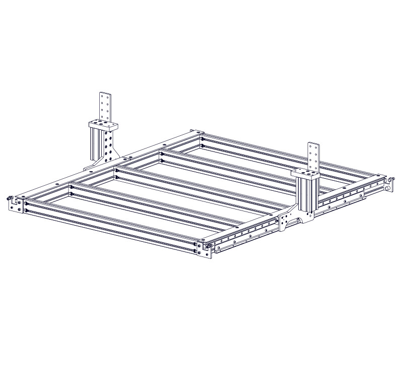
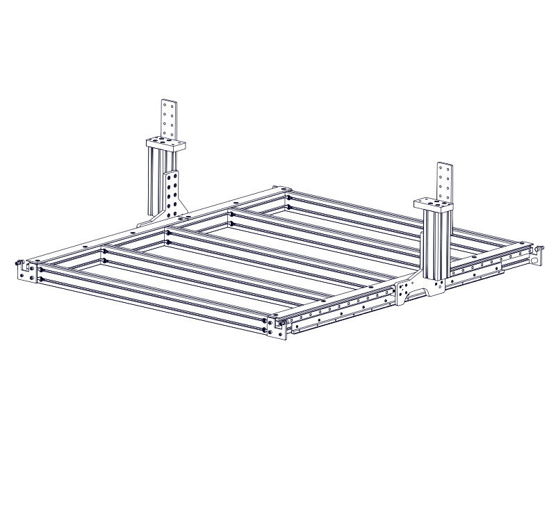
3.1 - Riser Installation


Parts List
| ID | QTY | Part/Description | Package Label | |
|---|---|---|---|---|
A | 2 | Riser Plate CRP820-01 | Gantry Assembly Kit | |
B | 2 | 8080 Riser Extrusion, 190mm (7-1/2") | 8080 Riser Extrusion, 290mm (11-7/16") | Gantry Assembly Kit |
C | 2 | Gantry Interface Plate CRP820-02 | Gantry Assembly Kit | |
D | 2 | Joining Plate CRP820-10 | Gantry Assembly Kit | |
1 | CRP820-00-FAST | Gantry Assembly Kit | ||
E | 16 12 | M5 x 10mm Socket Head Cap Screw | CRP820-00-FASTPackaged in | |
F | 32 | M8 x 20mm Socket Head Cap Screw | CRP820-00-FASTPackaged in | |
G | 32 | M8 Roll-in T-Nut | CRP820-00-FASTPackaged in | |
H | 8 | M8 x 35mm Flat Head Screw | CRP820-00-FASTPackaged in | |
J | 2 | Damper | CRP815-00-SRVPackaged in | |
K | 2 | Table Damper Mount | CRP815-00-SRVPackaged in | |
L | 4 | M5 x 20mm Socket Head Cap Screw | CRP815-00-SRVPackaged in | |
M | 4 | Hex Jam Nut | Included with Damper | |
| Remaining parts from CRP820-00-FAST used in future section | ||||
Tools List
| Requirement | Tool |
|---|---|
| Required | 4mm Allen Wrench |
| Required | 5mm Allen Wrench |
| Required | 6mm Allen Wrench |
| Required | Adjustable Wrench |
| Required | Tape Measure |
| Recommended | Metric Combination Wrench, 19mm |
3.1.1 - Riser Plate
3.1.1.1
- Install a Riser Plate A onto the Linear Bearing Blocks I using M5 x 10mm Socket Head Cap Screws E.
- Install the Table Damper Mount K using M5 x 20mm Socket Head Cap Screws L. Partially tighten the fasteners.
Assembly Note
The riser plates come as a pair, with a left and right configuration. Refer to the images to ensure the correct one is used.
3.1.1.2

- Ensure the Riser Plate sits flush on the linear bearing block reference edges.
- Fully tighten the fasteners.
3.1.1.3
- Partially thread M8 Roll-in T-Nuts G onto the Riser Plate using M8 x 20mm Socket Head Cap Screws F as indicated.
3.1.1.4
- Repeat this process to install a Riser Plate on the other side of the machine.
3.1.1.5
- Remove the Hex Jam Nut M from the end of the Damper J away from the plunger.
- Thread the Damper into the Damper mount. Adjust the Damper end location to be 10mm (3/8") from the front face of the gantry riser.
- Tighten Hex Jam Nut against the Damper mount.
- Perform this step on both the left and right sides of the machine.
3.1.1.6
- Move the gantry to the front of the machine.
- Push the gantry so that the Damper piston is just touching the Bumper Plate. If the plunger is not completely within the indentation on the plate, loosen the M8 socket head cap screws and adjust the plate so that the indentation lines up with the plunger.
- Retighten the M8 screws to lock the Bumper Plate in place.
- Perform this step on both the left and right sides of the machine.
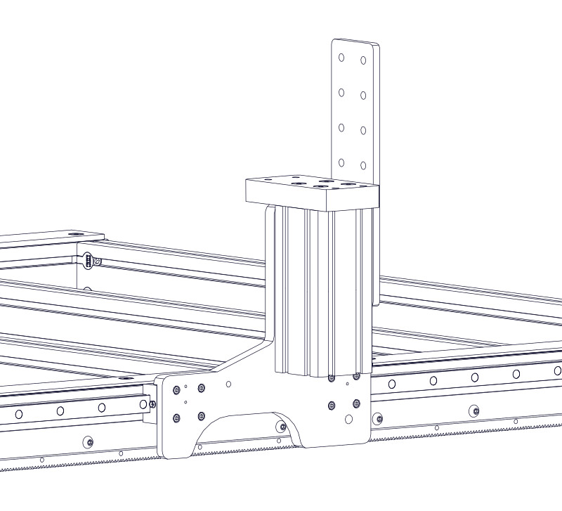
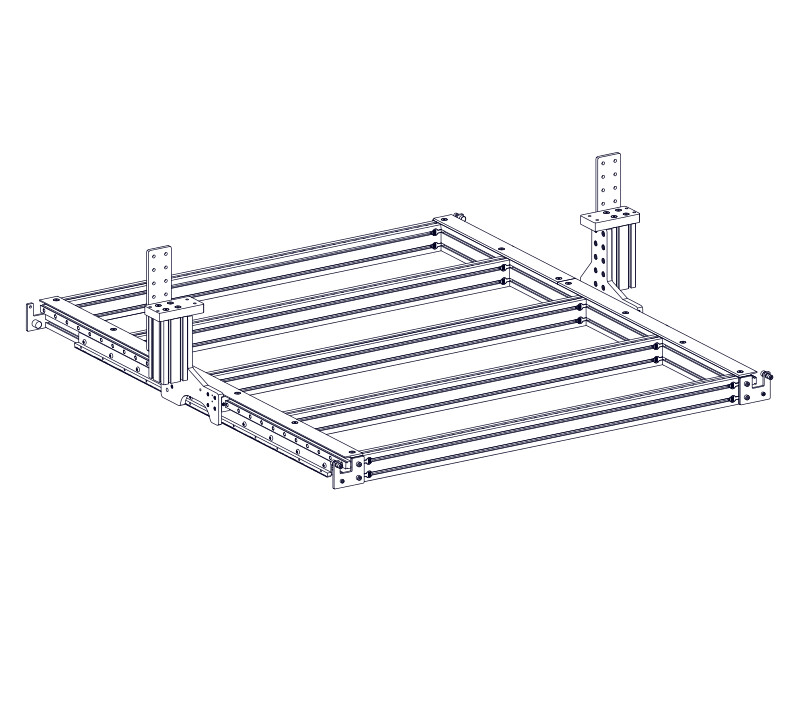
3.1.2 - Riser Extrusion
3.1.2.1
- Install a Gantry Interface Plate C onto the 8080 Riser Extrusion B using M8 x 35mm Flat Head Screws H.
- Fully tighten the fasteners.
3.1.2.2
- Slide the extrusion assembly from the previous step onto the riser plate t-nuts.
Assembly Note
Ensure the bottom of the t-nuts on the riser plate are facing up, as indicated, and the long side of the Gantry Interface Plate C is facing towards the inside of the machine.
3.1.2.3

- Bring the gantry interface plate flush with the top of the riser plate, as indicated.
3.1.2.4
- Fully tighten all ten M8 x 20mm Socket Head Cap Screw F riser plate fasteners.
3.1.2.5
- Install a Gantry Interface Plate C onto the 8080 Riser Extrusion B using M8 x 35mm Flat Head Screws H.
- Fully tighten the fasteners.
3.1.2.6
- Slide the extrusion assembly from the previous step onto the riser plate t-nuts.
Assembly Note
Ensure the bottom of the t-nuts on the riser plate are facing up, as indicated, and the long side of the Gantry Interface Plate C is facing towards the inside of the machine.
3.1.2.7

- Use a piece of dimensional lumber to position the riser extrusion. Determine the length of this spacer by subtracting 200mm (8") from your gantry height (this can be found in the description of your invoice or packing list). For example, the optional 12" gantry risers would need a 100mm (4") spacer.
3.1.2.8
-
Fully tighten all ten M8 x 20mm Socket Head Cap Screw F riser plate fasteners.
-
Remove dimensional lumber spacer.
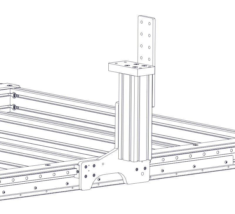
3.1.3 - Riser Joining Plate
3.1.3.1
- Partially thread M8 Roll-in T-Nuts G onto the CPR820-10 Joining Plate D using M8 x 20mm Socket Head Cap Screws F, as indicated.
3.1.3.2
- Slide the joining plate onto the riser extrusion.
3.1.3.3
- Position the top the joining plate 160mm (6-5/16") above the Gantry Interface Plate C.
- Tighten the two indicated fasteners (red arrows) to hold the joining plate in place.
3.1.3.4

- Repeat this process to assemble the riser on the other side of the machine.