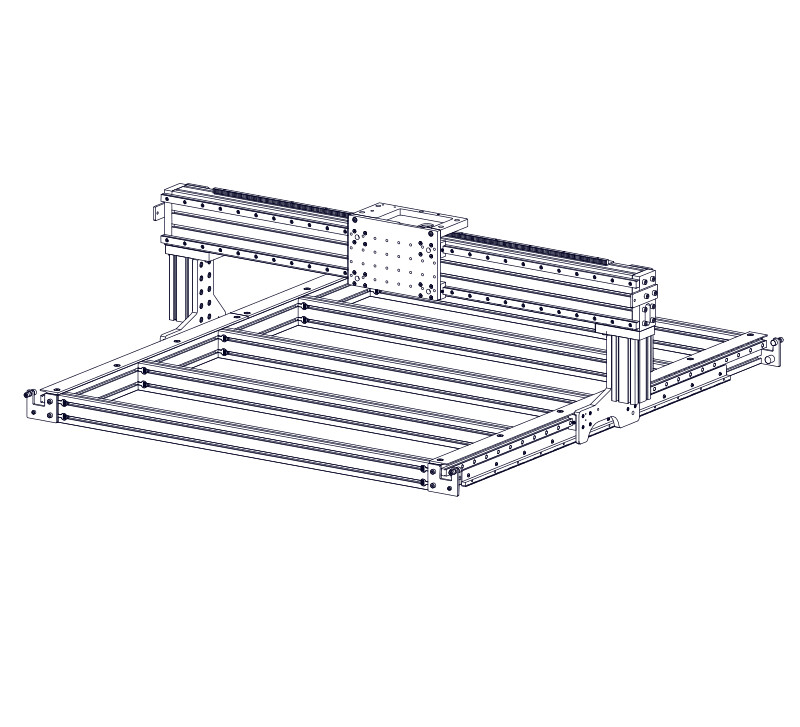
4. Gantry
Section Note
While some steps in this section show a standard gantry width machine, the assembly procedure in these steps is also applicable for extended gantries.
4.1 - Gantry Extrusion
Parts List
| ID | QTY | Part/Description | Package Label |
|---|---|---|---|
A | 1 | 8016 Gantry Extrusion, 950mm (37-3/8") 8016 Gantry Extrusion, 1250mm (49-1/4") 8016 Gantry Extrusion, 1550mm (61") 8016 Gantry Extrusion, 1850mm (72-13/16") 8016 Gantry Extrusion, 2150mm (84-5/8") 8016 Gantry Extrusion, 2500mm (98-7/16") 8016 Gantry Extrusion, 2800mm (110-1/4") 8016 Gantry Extrusion, 3100mm (122") | Machine Kit Extrusion |
1 | Gantry Hardware CRP830-00-HW | Gantry Assembly Kit | |
B | 1 | Gantry End Cap CRP830-03 | CRP830-00-HWPackaged in |
C | 6 | M8 x 35mm Socket Head Cap Screw | Gantry End Cap FastenersPackaged in |
1 | Riser Fasteners CRP820-00-FAST | Gantry Riser Hardware | |
D | 20 | M8 Roll-in T-Nut | CRP820-00-FASTPackaged in |
E | 4 | M8 x 35mm Socket Head Cap Screw | CRP820-00-FASTPackaged in |
F | 8 | M8 x 20mm Socket Head Cap Screw | CRP820-00-FASTPackaged in |
1 | CRP830-00-FAST-XTD | Gantry Assembly Kit | |
G | 4 | M8 Roll-in T-Nut | CRP830-00-FAST-XTDPackaged in |
| Remaining parts from CRP833-00-FAST and CRP820-00-FAST used in future section | |||
Tools List
| Requirement | Tool |
|---|---|
| Required | 6mm Allen Wrench |
4.1.1 - Extrusion Assembly
4.1.1.1
- Slide M8 Roll-in T-Nuts D into the 8016 Gantry Extrusion A T-Slots.
Assembly Note
Ensure the indicated (red arrows) t-nuts are in the correct orientation.
4.1.1.2


- Position the t-nuts to the dimensions shown.
Assembly Note
Dimensions shown are from the end of the extrusion to the center of the t-nut hole.
4.1.1.3
- Slide M8 Roll-in T-Nuts D G into the bottom gantry extrusion t-slots.
4.1.1.4


- Position the bottom t-nuts to the dimension shown.
Assembly Note
Dimensions shown are from the end of the extrusion to the center of the t-nut hole.
4.1.1.5
- Repeat these steps to install M8 Roll-in T-Nuts D G on the other end of the gantry extrusion.
4.1.1.6
- With the t-nuts in the extrusion facing you, install a Gantry End Cap B onto the right end of the extrusion using M8 x 35mm Socket Head Cap Screws C.
Assembly Note
Orient the gantry end cap with the tapped holes on the bottom biased towards the outside of the extrusion.
Assembly Note
Do not install fasteners in the remaining two holes of the gantry end cap; these will be used when mounting the gantry bumpers.
4.1.1.7
- Fully tighten the M8 x 35mm Socket Head Cap Screws C.
Assembly Note
Do not install the gantry end cap on the other side of the extrusion. You will need access to the extrusion t-slots in future steps.
4.1.2 - Extrusion Installation
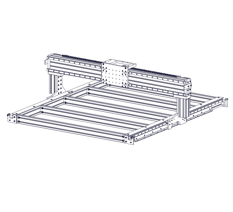
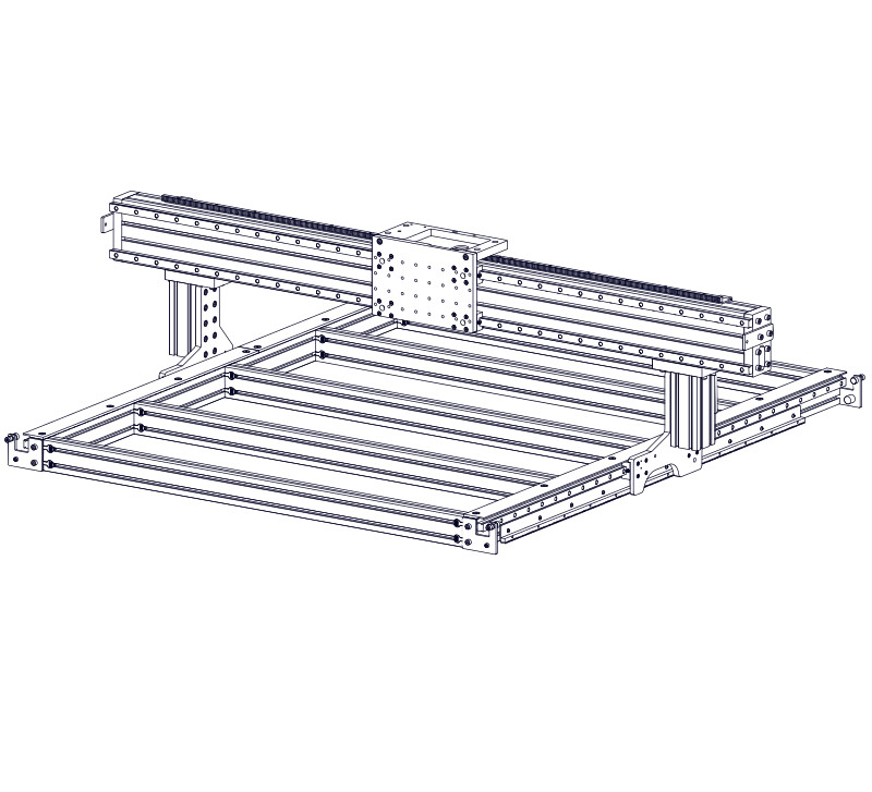
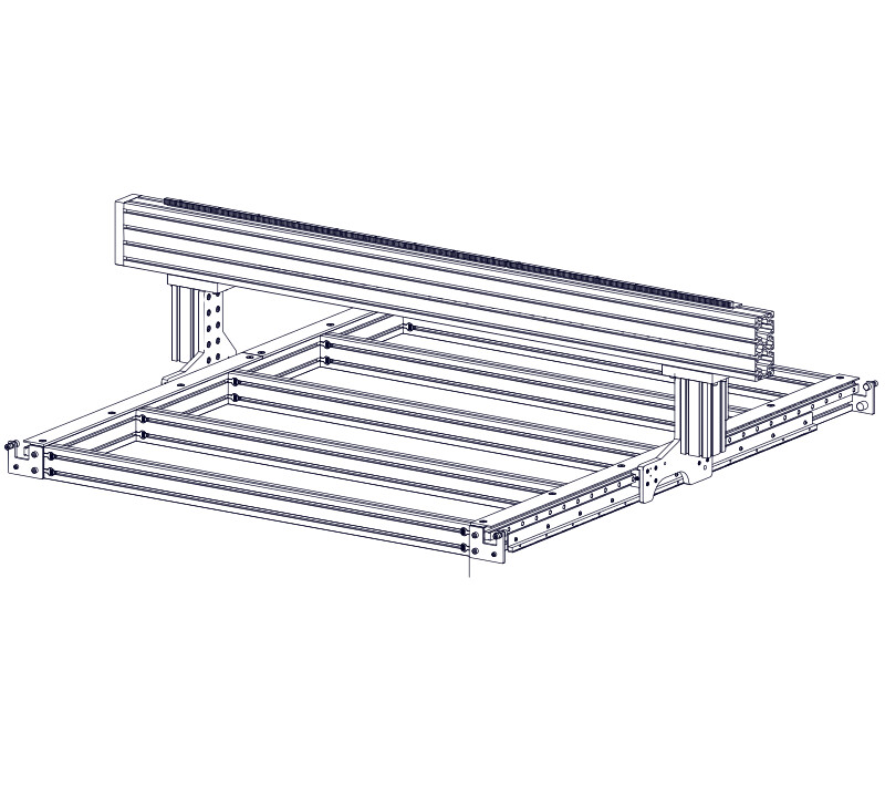
4.1.2.1


- Carefully lower the gantry extrusion onto the risers.
- Note the orientation of the extrusion, with the installed end cap on the indicated side.
Assembly Note
This step is made easier by sliding the risers to the front of the machine, as shown.
4.1.2.2
- Bring the Gantry End Cap B flush with the Gantry Interface Plate H , as shown.
- Position the gantry 150mm (5-7/8") from the Gantry Interface Plate H , as shown.
4.1.2.3
- On the side with the gantry end cap, attach the gantry using M8 x 35mm Socket Head Cap Screws E , partially tightening the fasteners.
Assembly Note
These fasteners thread into the t-nuts installed into the gantry extrusion in a previous step.
4.1.2.4
- Thread M8 x 20mm Socket Head Cap Screws F into the t-nuts, partially tightening the fasteners.
Assembly Note
Ensure the top of the joining plate is flush with the top of the gantry extrusion, as indicated by the red arrow.
4.1.2.5
- Fully tighten the four indicated M8 x 20mm Socket Head Cap Screws F .
4.1.2.6
- Fully tighten the remaining indicated M8 x 20mm Socket Head Cap Screws F .
4.1.2.7
- Fully tighten the M8 x 35mm Socket Head Cap Screws E .
4.2 - Gear Rack

Parts List
| ID | QTY | Part/Description | Package Label |
|---|---|---|---|
A | 1 | Gear Rack, 762mm (30") | Gantry Steel Kit |
1 | MGM-30-FAST-40 | Gantry Assembly Kit | |
C | 5 | M8 x 12mm Button Head Cap Screw | MGM-30-FAST-40Packaged in |
D | 5 | M8 Slide-in T-Nut | MGM-30-FAST-40Packaged in |
A | 1 | Gear Rack, 990mm (39") | Gantry Steel Kit |
1 | MGM-39-FAST-40 | Gantry Assembly Kit | |
C | 8 | M8 x 12mm Button Head Cap Screw | MGM-39-FAST-40Packaged in |
D | 8 | M8 Slide-in T-Nut | MGM-39-FAST-40Packaged in |
A | 1 | Gear Rack, 1320mm (52") | Gantry Steel Kit |
1 | MGM-52-FAST-40 | Gantry Assembly Kit | |
C | 10 | M8 x 12mm Button Head Cap Screw | MGM-52-FAST-40Packaged in |
D | 10 | M8 Slide-in T-Nut | MGM-52-FAST-40Packaged in |
A | 1 | Gear Rack, 660mm (26") | Gantry Steel Kit |
B | 1 | Gear Rack, 990mm (39") | Gantry Steel Kit |
1 | MGM-26-FAST-40 | Gantry Assembly Kit | |
C | 5 | M8 x 12mm Button Head Cap Screw | MGM-26-FAST-40Packaged in |
D | 5 | M8 Slide-in T-Nut | MGM-26-FAST-40Packaged in |
8 | MGM-39-FAST-40 | Gantry Assembly Kit | |
E | 8 | M8 x 12mm Button Head Cap Screw | MGM-39-FAST-40Packaged in |
F | 8 | M8 Slide-in T-Nut | MGM-39-FAST-40Packaged in |
A | 2 | Gear Rack, 990mm (39") | Gantry Steel Kit |
2 | MGM-39-FAST-40 | Gantry Assembly Kit | |
C | 16 | M8 x 12mm Button Head Cap Screw (8 per bag) | MGM-39-FAST-40Packaged in |
D | 16 | M8 Slide-in T-Nut (8 per bag) | MGM-39-FAST-40Packaged in |
A | 1 | Gear Rack, 990mm (39") | Gantry Steel Kit |
B | 1 | Gear Rack, 1320mm (52") | Gantry Steel Kit |
8 | MGM-39-FAST-40 | Gantry Assembly Kit | |
C | 8 | M8 x 12mm Button Head Cap Screw | MGM-39-FAST-40Packaged in |
D | 8 | M8 Slide-in T-Nut | MGM-39-FAST-40Packaged in |
1 | MGM-52-FAST-40 | Gantry Assembly Kit | |
E | 10 | M8 x 12mm Button Head Cap Screw | MGM-52-FAST-40Packaged in |
F | 10 | M8 Slide-in T-Nut | MGM-52-FAST-40Packaged in |
B | 2 | Gear Rack, 1320mm (52") | Gantry Steel Kit |
2 | MGM-52-FAST-40 | Gantry Assembly Kit | |
C | 20 | M8 x 12mm Button Head Cap Screw (10 per bag) | MGM-52-FAST-40Packaged in |
D | 20 | M8 Slide-in T-Nut (10 per bag) | MGM-52-FAST-40Packaged in |
B | 3 | Gear Rack, 990mm (39") | Gantry Steel Kit |
3 | MGM-52-FAST-40 | Gantry Assembly Kit | |
C | 24 | M8 x 12mm Button Head Cap Screw (8 per bag) | MGM-39-FAST-40Packaged in |
D | 24 | M8 Slide-in T-Nut (8 per bag) | MGM-39-FAST-40Packaged in |
Tools List
| Requirement | Tool |
|---|---|
| Required | 5mm Allen Wrench |
| Required | Tape Measure |
| Required | (2) Clamp |
4.2.1 - Gear Rack Assembly
4.2.1.1
- Partially thread M8 x 12mm Button Head Cap Screws C onto M8 Slide-in T-Nuts D , through the Gear Rack, 660mm (26") A Gear Rack, 762mm (30") A Gear Rack, 990mm (39") A Gear Rack, 1320mm (52") A .
4.2.1.2
- Partially thread M8 x 12mm Button Head Cap Screws E onto M8 Slide-in T-Nuts F , through the Gear Rack, 990mm (39") B Gear Rack, 1320mm (52") B .
- Repeat this process to assemble the second section of gear rack.
- Repeat this process to assemble the two more sections of gear rack.
4.2.2 - Gear Rack Installation
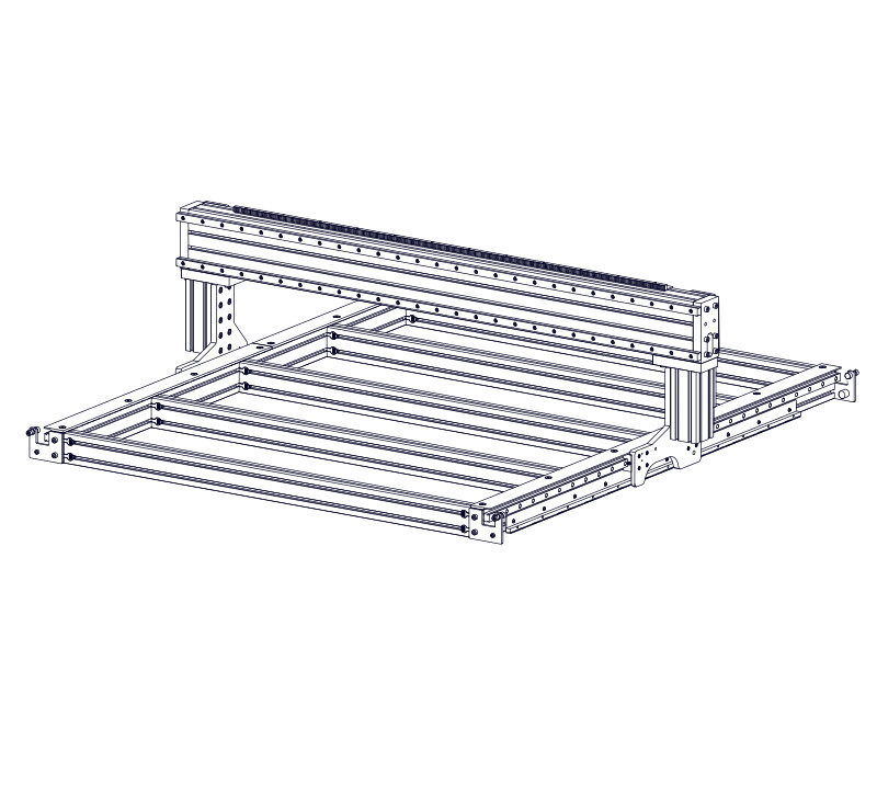
4.2.2.1
- Slide the an assembled section of gear rack into top rear t-slot of the gantry extrusion.
Assembly Note
Ensure the gear rack teeth are facing towards the front of the machine.
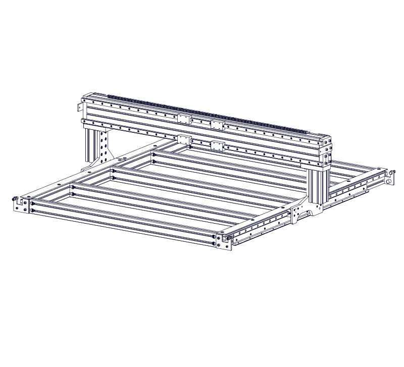
4.2.2.2


- Slide the second assembled gear rack section into the same t-slot.
- Slide the remaining two assembled gear rack sections into the same t-slot.
4.2.2.3


- Position the gear rack as indicated, from the right end of the gantry extrusion when looking from the front.
- Fully tighten all gear rack fasteners.
Assembly Note
Ensure your measurements are taken from the end of the gear rack and not the gear rack mounting flange.
4.2.2.4


- Fully tighten the fasteners on the gear rack section located on the right side of the gantry only.
4.2.2.5
- Clamp the Gear Rack Splice G to the first two sections to align the gear rack teeth.
4.2.2.6

- Start at the splice location and tighten the fasteners, working towards the opposite end of the gear rack.
- Remove clamps and gear rack splice.
- Repeat this process to align and fasten the third gear rack section.
4.3 - Linear Rails
Parts List
| ID | QTY | Part/Description | Package Label |
|---|---|---|---|
A | 2 | Linear Rail, 1000mm (39-3/8") Linear Rail, 1300mm (51-3/16") Linear Rail, 1600mm (63") Linear Rail, 1900mm (74-13/16") Linear Rail, 2200mm (86-5/8") Linear Rail, 2550mm (100-3/8") Linear Rail, 2850mm (112-3/16") Linear Rail, 3150mm (124") | Gantry Steel Kit |
2 | GH20-24-FAST GH20-36-FAST GH20-48-FAST GH20-60-FAST GH20-72-FAST GH20-84-FAST GH20-96-FAST GH20-108-FAST | Gantry Assembly Kit | |
B | 30 40 50 60 70 82 96 102 | M5 x 20mm Socket Head Cap Screw (15 per bag) M5 x 20mm Socket Head Cap Screw (20 per bag) M5 x 20mm Socket Head Cap Screw (25 per bag) M5 x 20mm Socket Head Cap Screw (30 per bag) M5 x 20mm Socket Head Cap Screw (35 per bag) M5 x 20mm Socket Head Cap Screw (41 per bag) M5 x 20mm Socket Head Cap Screw (48 per bag) M5 x 20mm Socket Head Cap Screw (51 per bag) | GH20-24-FASTGH20-36-FASTGH20-48-FASTGH20-60-FASTGH20-72-FASTGH20-84-FASTGH20-96-FASTGH20-108-FASTPackaged in |
C | 30 40 50 60 70 82 96 102 | M5 Slide-in T-Nut (15 per bag) M5 Slide-in T-Nut (20 per bag) M5 Slide-in T-Nut (25 per bag) M5 Slide-in T-Nut (30 per bag) M5 Slide-in T-Nut (35 per bag) M5 Slide-in T-Nut (41 per bag) M5 Slide-in T-Nut (48 per bag) M5 Slide-in T-Nut (51 per bag) | GH20-24-FASTGH20-36-FASTGH20-48-FASTGH20-60-FASTGH20-72-FASTGH20-84-FASTGH20-96-FASTGH20-108-FASTPackaged in |
1 | Gantry End Cap Kit CRP833-00 | Gantry Assembly Kit | |
D | 1 | Gantry End Cap CRP830-03 | CRP833-00Packaged in |
E | 6 | M8 x 35mm Socket Head Cap Screw | CRP833-00Packaged in |
1 | CRP820-00-FAST | Gantry Assembly Kit | |
F | 4 | M8 x 35mm Socket Head Cap Screw | CRP820-00-FASTPackaged in |
G | 8 | M8 x 20mm Socket Head Cap Screw | CRP820-00-FASTPackaged in |
1 | Linear Rail Setting Jig Kit | Base Hardware | |
H | 2 | Rail Alignment Jig | Linear Rail Setting Jig KitPackaged in |
I | 4 | M8 x 25mm Socket Head Cap Screw | Linear Rail Setting Jig KitPackaged in |
J | 4 | M8 Roll-in T-Nut | Linear Rail Setting Jig KitPackaged in |
K | 4 | Linear Bearing Block GHH20CA | Gantry Assembly Kit |
L | 4 | M6 Flush Mount Grease Fitting | Gantry Assembly Kit |
Tools List
| Requirement | Tool |
|---|---|
| Required | 4mm Allen Wrench |
| Required | 6mm Allen Wrench |
| Required | (2) Clamp |
4.3.1 - Linear Rail Assembly
4.3.1.1
- Partially thread M5 x 20mm Socket Head Cap Screws B onto M5 Slide-in T-Nuts C , through the Linear Rail, 1000mm (39-3/8") A . Linear Rail, 1300mm (51-3/16") A . Linear Rail, 1600mm (63") A . Linear Rail, 1900mm (74-13/16") A . Linear Rail, 2200mm (86-5/8") A . Linear Rail, 2550mm (100-3/8") A . Linear Rail, 2850mm (112-3/16") A . Linear Rail, 3150mm (124") A .
Assembly Note
The outermost hole on each side of the linear rail will not use a fastener.
4.3.1.2


- Repeat the previous step to assemble the second linear rail.
4.3.2 - Linear Rail Installation
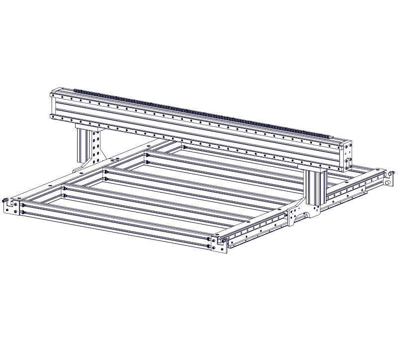
4.3.2.1
- Slide the assembled linear rails onto the front of the gantry extrusion, using the top and bottom t-slots.
4.3.2.2
- Install the Gantry End Cap D using M8 x 35mm Socket Head Cap Screws E .
- Fully tighten the fasteners.
Assembly Note
Orient the gantry end cap with the tapped holes on the bottom biased towards the outside of the machine.
Assembly Note
Do not install fasteners in the remaining two holes of the gantry end cap; these will be used when mounting the gantry bumpers.
4.3.2.3
- Install and partially tighten the indicated M8 x 35mm Socket Head Cap Screws F .
4.3.2.4
- Install and partially tighten the remaining M8 x 20mm Socket Head Cap Screws G into the gantry extrusion.
Assembly Note
Ensure the top of the joining plate is flush with the top of the gantry extrusion, as indicated by the red arrow.
4.3.2.5
- Fully tighten the four indicated M8 x 20mm Socket Head Cap Screws G .
4.3.2.6
- Fully tighten the remaining indicated M8 x 20mm Socket Head Cap Screws G .
4.3.2.7
- Fully tighten the M8 x 35mm Socket Head Cap Screws F .
4.3.3 - Linear Rail Alignment
4.3.3.1
- Attach the Rail Alignment Jig H using M8 x 25mm Socket Head Cap Screws I and M8 Roll-in T-Nuts J .
4.3.3.2

- Clamp the end of the linear rail to the rail alignment jig as indicated.
4.3.3.3

- Repeat this process to clamp the other side of the linear rail.
4.3.3.4

- Fully tighten the linear rail fasteners only on the clamped linear rail.
- After tightening, remove the clamps and rail alignment jigs.
Assembly Note
Partially tighten the lower linear rail fasteners. These will be fully tightened after the gantry carriage assembly is installed.
4.3.4 - Linear Bearing Block Installation
4.3.4.1
- Thread Grease Fittings L into the Linear Bearing Blocks K as indicated and hand tighten.
- Orientation of the linear bearing block reference edges is not important for installation on the gantry.
Assembly Note
DO NOT remove the plastic bearing retainers at this time.
4.3.4.2
- Slide the linear bearing blocks onto the rails as indicated, with the grease fittings facing away from each other.
Assembly Note
Refer to the Base ComponentsBase Components section for the correct procedure to remove the plastic bearing retainers.
Assembly Note
Follow the same procedure used in the Base ComponentsBase Components to grease the linear bearing blocks.
4.4 - Gantry Bumper Plates & Sensor Flags

Parts list
| ID | QTY | Part/Description | Package Label |
|---|---|---|---|
1 | Bumper and Motor Hardware Kit CRP815-00-N23 CRP815-00-N34 CRP815-00-SRV | Gantry Assembly Kit | |
A | 1 2 | PRO Gantry Axis Bumper Plate | CRP815-00-N23CRP815-00-N34CRP815-00-SRVPackaged in |
B | 1 | PRO Gantry Axis Bumper Plate, Servo | CRP815-00-SRVPackaged in |
C | 2 | M8 x 50mm Socket Head Cap Screw | CRP815-00-N23CRP815-00-N34CRP815-00-SRVPackaged in |
D | 2 | M8 x 60mm Socket Head Cap Screw | CRP815-00-N23CRP815-00-N34CRP815-00-SRVPackaged in |
E | 1 | Gantry Bumper Shim | CRP815-00-N23CRP815-00-N34CRP815-00-SRVPackaged in |
1 | Gantry Sensor Flag Kit CRP831-02-00 | Gantry Assembly Kit | |
F | 4 | M8 Roll-in T-Nut | CRP831-02-00Packaged in |
G | 4 | M8 x 25mm Socket Head Cap Screw | CRP831-02-00Packaged in |
H | 2 | Sensor Flag CRP831-02 | CRP831-02-00Packaged in |
| Remaining parts from CRP815-00 used in future section | |||
Tools List
| Requirement | Tool |
|---|---|
| Required | 6mm Allen Wrench |
4.4.1 - Bumper Plate Installation
4.4.1.1
- Attach the PRO Gantry Axis Bumper Plate, Servo BA and Gantry Bumper Shim E to the gantry end cap using M8 x 60mm Socket Head Cap Screws D on left side of gantry.
Assembly Note
If you intend to mount the Tool Height Setter on the right side of the machine, use the Gantry Bumper Shim and M8 x 60mm Socket Head Cap Screws in the next step and use the M8 x 50mm Socket Head Cap Screws in this step.
4.4.1.2
- Attach the PRO Gantry Axis Bumper Plate A to the gantry end cap using M8 x 50mm Socket Head Cap Screws C .
Assembly Note
The rubber bumpers will be installed on the bumper plate after installation of proximity sensors in Section 9.
4.4.2 - Gantry Sensor Flag Installation
4.4.2.1
- Attach a Sensor Flag H to each end of the gantry, outside the joining plates, using M8 x 25mm Socket Head Cap Screws G and M8 Roll-in T-Nuts F , partially tightening the fasteners.
4.4.2.2


- Position the gantry sensor flags according to the table below, based on which side you installed your shim plate under the gantry bumper.
| Flag | Shim Located on Left | Shim Located on Right |
|---|---|---|
| Left Sensor Flag | 22.5mm (7/8") | 32mm (1-1/4") |
| Right Sensor Flag | 38mm (1-1/2") | 28.5mm (1-1/8") |
| Flag | Shim Located on Left | Shim Located on Right |
|---|---|---|
| Left Sensor Flag | 16mm (5/8") | 6.5mm (1/4") |
| Right Sensor Flag | 0mm (0") | 9.5mm (3/8") |
| Flag | Shim Located on Left | Shim Located on Right |
|---|---|---|
| Left Sensor Flag | 28.5mm (1-1/8") | 38mm (1-1/2") |
| Right Sensor Flag | 38mm (1-1/2") | 28.5mm (1-1/8") |
| Flag | Shim Located on Left | Shim Located on Right |
|---|---|---|
| Left Sensor Flag | 9.5mm (3/8") | 0mm (0") |
| Right Sensor Flag | 0mm (0") | 9.5mm (3/8") |
Note
Right and left are based on viewing the machine from the front.
4.4.2.3

- Bias the sensor flags towards the top of the gantry extrusion.
- Fully tighten the sensor flag fasteners.
4.5 - Gantry Carriage
Parts List
| ID | QTY | Part/Description | Package Label |
|---|---|---|---|
A | 1 | Gantry Plate CRP830-01 | Gantry Assembly Kit |
B | 1 | Gantry R&P Plate CRP830-02 | Gantry Assembly Kit |
1 | CRP832-00-FAST | Gantry Assembly Kit | |
C | 16 | M5 x 22mm Flat Head Cap Screw | CRP832-00-FASTPackaged in |
D | 2 | M8 x 20mm Dowel Pin | CRP832-00-FASTPackaged in |
E | 2 | M8 x 20mm Socket Head Cap Screw | CRP832-00-FASTPackaged in |
F | 1 | Gantry Damper Mount | CRP815-00-SRVPackaged in |
G | 1 | M8 x 16mm Hex Cap Screw | CRP815-00-SRVPackaged in |
H | 1 | Damper | CRP815-00-SRVPackaged in |
I | 2 | Hex Jam Nut | Included with Damper |
Tools List
| Requirement | Tool |
|---|---|
| Required | 4mm Allen Wrench |
| Required | 6mm Allen Wrench |
| Required | Adjustable Wrench |
| Recommended | Metric Combination Wrenches 13mm, 19mm |
| Recommended | Metric Ratcheting Box Wrench, 13mm |
4.5.1 - Gantry Carriage Installation
4.5.1.1
- Attach the Gantry Damper Mount F to the Gantry Plate A using the M8 x 16mm Hex Cap Screw G.
4.5.1.2
- Thread the Damper H into the Damper Mount so that the face of the damper is 9.5mm (3/8") from the end of the Gantry Plate as shown.
- Thread the Hex Jam Nut I onto the damper to lock it in position.
4.5.1.3
- Attach the Gantry Plate A to the linear bearing blocks using M5 x 22mm Flat Head Screws C .
Assembly Note
Ensure correct orientation of the gantry plate. The cutout on the back of the plate will be on the top and facing towards the gantry.
4.5.1.4

- Slide the gantry plate to one end of the gantry.
- Tighten the three indicated linear rail fasteners near the gantry plate.
4.5.1.5

- Slide the gantry plate to the other end of the gantry.
- Tighten the three indicated linear rail fasteners near the gantry plate.
4.5.1.6

- Fully tighten the remaining lower linear rail fasteners.
Assembly Note
You will need to move the gantry plate along the gantry to access all of the fasteners. During this operation it will be normal to feel some resistance.
Assembly Note
Linear rail hole covers are provided in your base hardware kit. We recommend that you install these covers after your machine is fully assembled and running.
4.5.1.7
- Install M8 x 20mm Dowel Pins D into the Gantry R&P Plate B as indicated.
4.5.1.8
- Attach the Gantry R&P Plate to the gantry plate using M8 x 20mm Socket Head Cap Screws E .
- Fully tighten the fasteners.
4.5.1.9
- Move the gantry carriage to the left side of the gantry.
- Push the gantry carriage so that the damper plunger is just touching the bumper plate. If the plunger is not completely within the indentation on the plate, loosen the M8 socket head cap screws and adjust the plate so that the indentation lines up with the plunger.
- Retighten the M8 screws to lock the bumper plate in place.
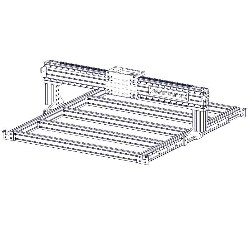
4.6 - Avid CNC Nameplate
Parts List
| ID | QTY | Part/Description | Package Label |
|---|---|---|---|
A | 1 | Avid CNC Nameplate | Gantry Cable Track Kit |
1 | Machine Name Plate Hardware CRP834-00-HW | Gantry Cable Track Kit | |
B | 4 | M5 x 12mm Flat Head Screw | CRP834-00-HWPackaged in |
C | 4 | M5 Roll-in T-Nut | CRP834-00-HWPackaged in |
Tools List
| Requirement | Tool |
|---|---|
| Required | 3mm Allen Wrench |
| Required | Tape Measure |
4.6.1 - Nameplate Installation
4.6.1.1
- Attach the Avid CNC Nameplate A to the gantry extrusion using M5 x 12mm Flat Head Screws B and M5 Roll-in T-Nuts C .
- Partially tighten the fasteners.
4.6.1.2

- Position the nameplate approximately 150mm (6") from the end of the gantry.
- Fully tighten the fasteners.
Assembly Note
This dimension is not critical; the nameplate can be positioned anywhere along the gantry.