6. Z Axis


6.1 - Z Axis Installation


Parts List
| ID | QTY | Part/Description | Package Label | |||
|---|---|---|---|---|---|---|
A | 1 | Ballscrew Z Axis CRP840-00 | Z Axis | |||
B | 1 | NEMA 23 Motor | NEMA 34 Motor | Z-axis Motor | Motor Set | |
1 | Z Axis Fastener Kit CRP840-00-FAST-250-24.2 | Z Axis Fastener Kit CRP840-00-FAST-375-24.2 | Z Axis Fastener Kit CRP840-00-FAST-500-24.2 | Z Axis Fastener Kit CRP840-00-FAST-SRV-24.2 | Bumper and Motor Hardware Kit | |
C | 1 | Oldham Coupler | CRP840-00-FAST-250-24.2CRP840-00-FAST-375-24.2CRP840-00-FAST-500-24.2CRP840-00-FAST-SRV-24.2Packaged in Bumper and Motor Hardware Kit | |||
D | 8 | M8 x 25mm Flat Head Screw | CRP840-00-FAST-250-24.2CRP840-00-FAST-375-24.2CRP840-00-FAST-500-24.2CRP840-00-FAST-SRV-24.2Packaged in Bumper and Motor Hardware Kit | |||
E | 4 | M5 x 10mm Socket Head Cap Screw | M5 x 18mm Socket Head Cap Screw | M5 x 14mm Socket Head Cap Screw | CRP840-00-FAST-250-24.2CRP840-00-FAST-375-24.2CRP840-00-FAST-500-24.2CRP840-00-FAST-SRV-24.2Packaged in Bumper and Motor Hardware Kit | |
K | 1 | M5 x 30mm Socket Head Cap Screw | Damper | CRP840-00-FAST-500-24.2CRP840-00-FAST-SRV-24.2Packaged in Bumper and Motor Hardware Kit | ||
L | 1 | Recess Bumper, 3/4" | CRP840-00-FAST-500-24.2Packaged in Bumper and Motor Hardware Kit | |||
L | 2 | Damper Nut | Included with Damper | |||
M | 1 | Aluminum Spacer | CRP840-00-FAST-500-24.2Packaged in Bumper and Motor Hardware Kit | |||
M | 1 | Motor Shaft Key | (pre-installed on Motor) | |||
N | 1 | Bumper Adapter Bushing | CRP840-00-FAST-500-24.2Packaged in Bumper and Motor Hardware Kit | |||
O | 4 | M5 Washer | CRP840-00-FAST-500-24.2CRP840-00-FAST-SRV-24.2Packaged in Bumper and Motor Hardware Kit | |||
P | 2 | M5 x 14mm Socket Head Cap Screw | Z Axis | |||
Q | 1 | Z Axis Brake Connector | Z Axis | |||
| Remaining parts from CRP840-00-FAST are not used | ||||||
| ID | QTY | Part/Description | Package Label | |||
|---|---|---|---|---|---|---|
A | 2 | Ballscrew Z Axis CRP840-00 | Z Axis | |||
B | 2 | NEMA 34 Motor | NEMA 23 Motor | Z-axis Motor | Motor Set | |
2 | Z Axis Fastener Kit CRP840-00-FAST-250-24.2 | Z Axis Fastener Kit CRP840-00-FAST-375-24.2 | Z Axis Fastener Kit CRP840-00-FAST-500-24.2 | Z Axis Fastener Kit CRP840-00-FAST-SRV-24.2 | Bumper and Motor Hardware Kit | |
C | 2 | Oldham Coupler | CRP840-00-FAST-250-24.2CRP840-00-FAST-375-24.2CRP840-00-FAST-500-24.2CRP840-00-FAST-SRV-24.2Packaged in Bumper and Motor Hardware Kit | |||
D | 16 | M8 x 25mm Flat Head Screw (8 per bag) | CRP840-00-FAST-250-24.2CRP840-00-FAST-375-24.2CRP840-00-FAST-500-24.2CRP840-00-FAST-SRV-24.2Packaged in Bumper and Motor Hardware Kit | |||
E | 8 | M5 x 10mm Socket Head Cap Screw (4 per bag) | M5 x 18mm Socket Head Cap Screw (4 per bag) | M5 x 14mm Socket Head Cap Screw (4 per bag) | CRP840-00-FAST-250-24.2CRP840-00-FAST-375-24.2CRP840-00-FAST-500-24.2CRP840-00-FAST-SRV-24.2Packaged in Bumper and Motor Hardware Kit | |
K | 2 | M5 x 30mm Socket Head Cap Screw | Damper | CRP840-00-FAST-500-24.2CRP840-00-FAST-SRV-24.2Packaged in Bumper and Motor Hardware Kit | ||
L | 2 | Recess Bumper, 3/4" | CRP840-00-FAST-500-24.2Packaged in Bumper and Motor Hardware Kit | |||
L | 4 | Damper Nut | Included with Damper | |||
M | 2 | Aluminum Spacer | CRP840-00-FAST-500-24.2Packaged in Bumper and Motor Hardware Kit | |||
M | 2 | Motor Shaft Key | (pre-installed on Motor) | |||
N | 2 | Bumper Adapter Bushing | CRP840-00-FAST-500-24.2Packaged in Bumper and Motor Hardware Kit | |||
O | 8 | M5 Washer | CRP840-00-FAST-500-24.2CRP840-00-FAST-SRV-24.2Packaged in Bumper and Motor Hardware Kit | |||
P | 4 | M5 x 14mm Socket Head Cap Screw | Z Axis | |||
Q | 2 | Z Axis Brake Connector | Z Axis | |||
| Remaining parts from CRP840-00-FAST are not used | ||||||
Tools List
| Requirement | Tool |
|---|---|
| Required | 2.5mm Allen Wrench |
| Required | 3mm Allen Wrench |
| Required | 4mm Allen Wrench |
| Required | 5mm Allen Wrench |
| Required | Adjustable Wrench |
| Required | Small Phillips Screwdriver (PH1) |
| Required | Tape Measure |
| Recommended | 14mm Combination Wrench |
6.1.1 - Z Axis Attachment
6.1.1.1
- Remove lower Damper Nut L from the Damper K.
- Install Damper in end plate and thread lower nut onto Damper. Adjust the Damper position so that the face of the Damper is 16mm (5/8") from the motor mount plate, as shown.
- Repeat the Damper installation steps for each Z axis.
- Install the M5 x 30mm Socket Head Cap Screw K through the Recess Bumper L, Aluminum Spacer M and thread into the Bumper Adapter Bushing N through the Z axis end plate, as indicated.
- Tighten the M5 x 30mm Socket Head Cap Screw K.
- Repeat the bumper installation steps for each Z axis.
6.1.1.2
- The Z-axis Brake Connector Q will arrive connected to the axis by two wires, but not attached to the motor mount plate.
- Line up the Z-axis Brake Connector with the two holes on the motor mount plate, as shown. Ensure that the alignment tab in the M12 panel mount (inset) is toward the front of the z-axis (the side the cutting tool mounts to). Tuck excess wire in the pocket on the top of the motor mount plate.
- Attach the brake connector with the M5 x 14mm Socket Head Cap Screws P. Do not overtighten the screws.
- Repeat these installation steps for the second Z axis.
6.1.1.3
- Secure the brake wire slack using the M3 Flat Head Machine Screw to lightly pinch the wires.
6.1.1.4
- Remove the pre-installed moving plate screws F holding the moving plate G to the Z axis.
Assembly Note
Place these screws aside, you will be reinstalling the moving plate in a future step.
Section Note
Your Z axis may look slightly different than the images. The assembly and installation procedure are the same.
6.1.1.5

- Remove the moving plate and set aside.
Assembly Note
Some force may be required to remove the moving plate from the Z axis.
6.1.1.6
- Remove the pre-installed dust cover screws H holding the metal dust covers to the Z axis.
Assembly Note
The remaining screws for the dust covers are included in a bag with the Z axis.
6.1.1.7
- Remove the metal dust covers J.
Assembly Note
Set aside the dust cover and screws that were removed, these will be reinstalled after mounting the Z axis.

6.1.1.9
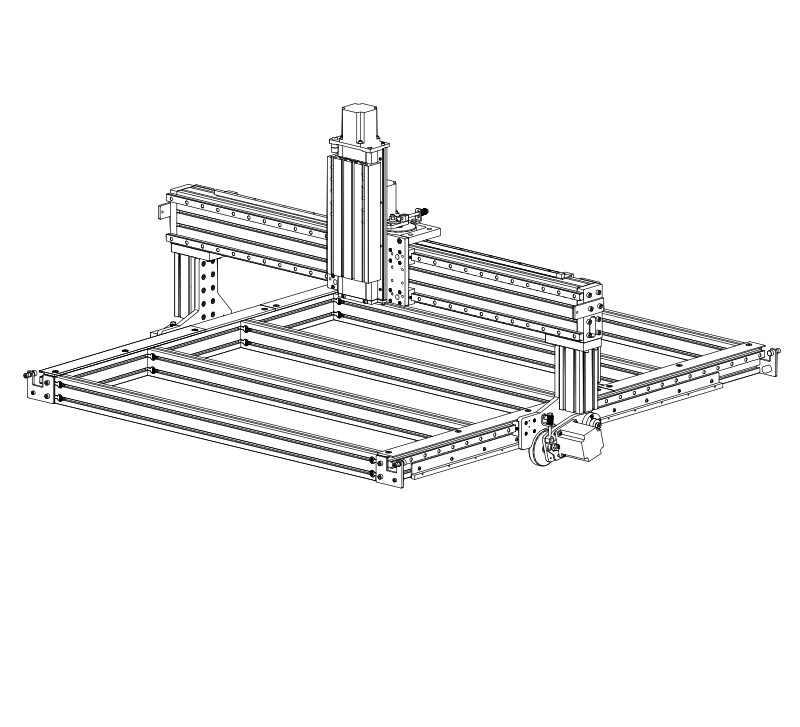
- Attach the Ballscrew Z Axis A to the gantry plate using M8 x 25mm Flat Head Screws D.
- Fully tighten all eight fasteners.
6.1.1.10
- Slide the metal dust covers J (removed in previous steps) back on the Z axis as indicated.
6.1.1.11
- Attach the metal dust covers using the dust cover screws H removed in previous steps.
Optional extended Z Axis
If installing a 12" Z axis, you will install 10 dust cover screws.
6.1.1.12
- Attach the moving plate G to the Z axis using the moving plate screws F removed in previous steps.
6.1.1.13
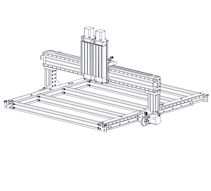
- Attach the first Ballscrew Z Axis A to the left side of the gantry plate using M8 x 25mm Flat Head Screws D.
- Fully tighten all eight fasteners.
6.1.1.14
- Attach the second Ballscrew Z Axis A to the right side of the gantry plate using M8 x 25mm Flat Head Screws D.
- Fully tighten all eight fasteners.
6.1.1.15
- Slide one metal dust cover J (from the bottom) onto the left Z axis, as shown.
Assembly Note
Wait to install the metal dust cover screws. This will be done in a later step.
6.1.1.16
- Slide a second metal dust cover J (from the bottom) onto the right Z axis, as shown.
6.1.1.17
- Fasten the metal dust covers using the dust cover screws H removed in previous steps.
Optional extended Z Axis
If installing a 12" Z axis, you will install 10 dust cover screws.
6.1.1.18
- Slide the remaining two metal dust covers J (from the side) onto the Z axes and fasten using the metal dust cover screws H.
Optional extended Z Axis
If installing a 12" Z axis, you will install 10 dust cover screws.
6.1.1.19
- Attach a moving plate G to each Z axis using the moving plate screws F removed in previous steps.
6.1.2 - Motor Installation
6.1.2.1
- Slide the motor half of the Oldham Coupler C onto the NEMA 23 Motor B as indicated.
Assembly Note
Align the key in the motor shaft with the slot in the Oldham coupler.
6.1.2.2
- Position the Oldham coupler to the dimension shown.
- Tighten the pre-installed clamping screw I on the Oldham coupler.
Assembly Note
The dimension shown is from the bottom of the motor boss to the top of the Oldham coupler.
6.1.2.3
- Install the assembled NEMA 23 Motor B onto the Z axis using M5 x 10mm Socket Head Cap Screws E.
Assembly Note
Orient the motor with the motor cable towards the back of the machine.

6.1.2.5
- Slide the motor half of the Oldham Coupler C onto the NEMA 34 Motor A as indicated.
Assembly Note
Align the key in the motor shaft with the slot in the Oldham coupler.
6.1.2.6
- Position the Oldham coupler to the dimension shown.
- Tighten the pre-installed clamping screw I on the Oldham coupler.
Assembly Note
The dimension shown is from the bottom of the motor boss to the top of the Oldham coupler.
6.1.2.7
- Install the assembled NEMA 34 Motor B onto the Z axis using M5 x 18mm Socket Head Cap Screws E and M5 Washers O .
Assembly Note
Orient the motor with the motor cable towards the back of the machine.

6.1.2.9
- Ensure the Motor Shaft Key M is securely installed onto the Z-axis Motor B shaft.
- Slide the motor half of the Oldham Coupler C onto the Motor as indicated.
Assembly Note
Align the key in the motor shaft with the slot in the Oldham coupler.
6.1.2.10
- Position the Oldham coupler to the dimension shown.
- Tighten the pre-installed clamping screw I on the Oldham coupler.
Assembly Note
The dimension shown is from the bottom of the motor boss to the top of the Oldham coupler.
6.1.2.11
- Install the assembled Z-axis Motor B onto the Z axis using M5 x 14mm Socket Head Cap Screws E and M5 Washers O .
Assembly Note
Orient the motor with the motor cable plugs towards the back of the machine.