7. Cable Track
Section Note
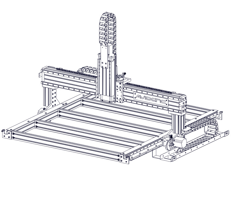
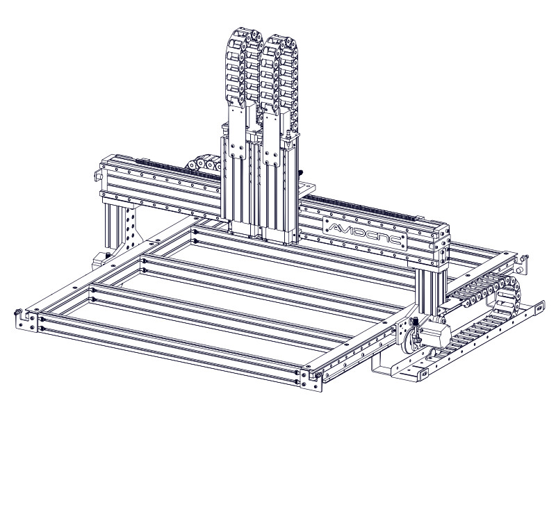
Images may not be representative of actual machine size and motor selection, however assembly steps and parts lists are specific for the machine configuration selected.
7.1 - Table Cable Track
Parts List
| ID | QTY | Part/Description | Package Label |
|---|---|---|---|
A | Cable Track Tray QT40x125B | Table Cable Track Kit | |
B | 1 | Cable Track Tray (short) QT40x125BS | Table Cable Track Kit |
C | Cable Tray Bracket CRP150-03 | Table Cable Track Kit | |
D | 1 | Riser Cable Track Bracket CRP150-08 | Table Cable Track Kit |
E | 1 | 75mm Cable Track Section | Table Cable Track Kit |
1 | Cable Track Base Fasteners CT-PRO-FAST-20.2 | Table Cable Track Kit | |
F | 2 | M8 x 12mm Button Head Cap Screw | CT-PRO-FAST-20.2Packaged in |
G | 2 | M8 Roll-in T-Nut | CT-PRO-FAST-20.2Packaged in |
H | 2 | M6 x 12mm Flat Head Screw | CT-PRO-FAST-20.2Packaged in |
J | 2 | M6 Hex Jam Nut | CT-PRO-FAST-20.2Packaged in |
Table Cable Tray Fasteners CT-TRAY-TABLE-PRO-FAST-20.2 | Table Cable Track Kit | ||
K | M8 x 12mm Button Head Cap Screw M8 x 12mm Button Head Cap Screw (2 per bag) | CT-TRAY-TABLE-PRO-FAST-20.2Packaged in | |
L | M8 x 16mm Socket Head Cap Screw M8 x 16mm Socket Head Cap Screw (4 per bag) | CT-TRAY-TABLE-PRO-FAST-20.2Packaged in | |
M | M8 Roll-in T-Nut M8 Roll-in T-Nut (4 per bag) | CT-TRAY-TABLE-PRO-FAST-20.2Packaged in | |
N | M8 Hex Flange Nut M8 Hex Flange Nut (2 per bag) | CT-TRAY-TABLE-PRO-FAST-20.2Packaged in | |
| Remaining parts from CT-PRO-FAST-20.2 used in future section | |||
Tools List
| Requirement | Tool |
|---|---|
| Required | 4mm Allen Wrench |
| Required | 5mm Allen Wrench |
| Required | 6mm Allen Wrench |
| Required | Adjustable Wrench |
| Required | Tape Measure |
| Recommended | 10mm Combination Wrench |
| Recommended | 13mm Combination Wrench |
7.1.1 - Cable Track Tray Installation
7.1.1.1
- Attach a Cable Tray Bracket C to the underside of the table extrusion using M8 x 16mm Socket Head Cap Screws L and M8 Roll-in T-Nuts M .
- Only partially tighten the fasteners to allow positioning in next steps.
Alternate Cable Track Location
If locating the table cable track on the left side of the machine, install the cable tray brackets on the left side of the machine.
7.1.1.2


- Repeat the previous step to attach the remaining cable tray brackets and position as indicated.
- Fully tighten the fasteners.
Assembly Note
Dimensions shown are from the back of the machine.
7.1.1.3
- Attach the Cable Track Tray (short) B to the cable tray brackets using M8 x 12mm Button Head Cap Screws K and M8 Hex Flange Nuts N .
- Attach the Cable Track Tray A to the cable tray brackets using M8 x 12mm Button Head Cap Screws K and M8 Hex Flange Nuts N .
- Attach the Cable Track Tray A and Cable Track Tray (short) B to the cable tray brackets using M8 x 12mm Button Head Cap Screws K and M8 Hex Flange Nuts N .
- Attach two Cable Track Trays A to the cable tray brackets using M8 x 12mm Button Head Cap Screws K and M8 Hex Flange Nuts N .
7.1.1.4
- Attach two Cable Tray Brackets C to the underside of the table extrusion using M8 x 16mm Socket Head Cap Screws L and M8 Roll-in T-Nuts M .
- Only partially tighten the fasteners to allow positioning in next steps.
7.1.1.5
- Attach a Cable Track Tray A to the cable tray brackets using M8 x 12mm Button Head Cap Screws K and M8 Hex Flange Nuts N .
7.1.1.6

- In the next steps, the remaining cable track trays will be installed and positioned. Depending on your machine length, position of legs, and location of extrusion splice bars, you may need to adjust the cable tray bracket mounting locations. There are two methods for this adjustment.
- Moving the location of the cable tray bracket along the extrusion T-Slot.
- Using a different mounting hole in the cable track tray.
7.1.1.7


- Using the procedure in the previous steps, install an additional two cable track trays.
- Using the procedure in the previous steps, install an additional three cable track trays.
- Using the procedure in the previous steps, install an additional four cable track trays.
- Using the procedure in the previous steps, install an additional five cable track trays.
- Using the procedure in the previous steps, install an additional six cable track trays.
- Using the procedure in the previous steps, install an additional seven cable track trays.
- Using the procedure in the previous steps, install an additional eight cable track trays.
- Using the procedure in the previous steps, install an additional nine cable track trays.
7.1.1.8

- Starting about 1000mm (40") from the front of the machine, evenly space (roughly) the cable track trays.
- Fully tighten the fasteners.
Assembly Note
This image may not reflect the actual number of cable track trays used for your length of machine.
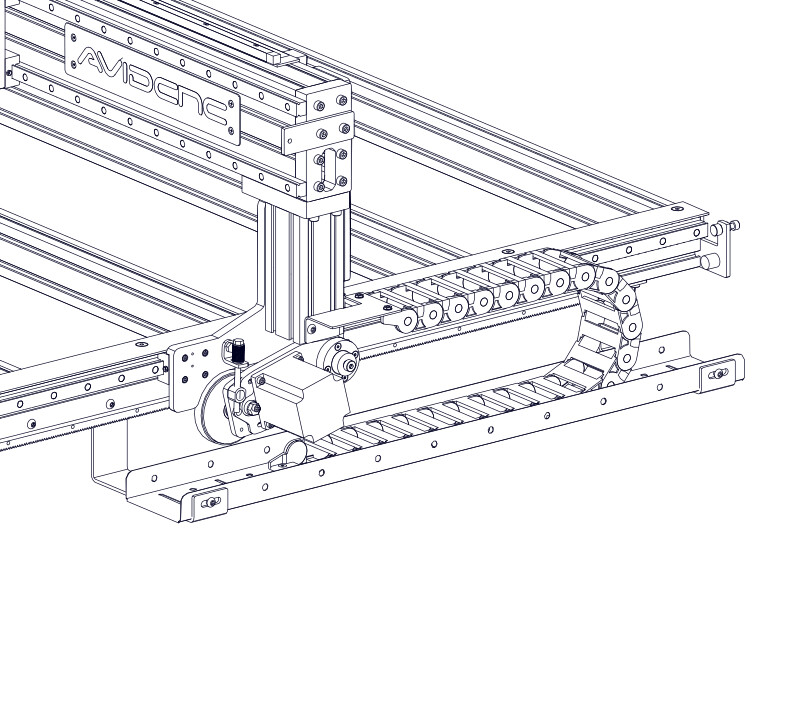
7.1.2 - Cable Track Installation
7.1.2.1
- Partially thread M8 x 12mm Button Head Cap Screws F onto M8 Roll-in T-Nuts G , through the Riser Cable Track Bracket D .
7.1.2.2
- Slide the assembled riser cable track bracket into the riser extrusion, as indicated.
Alternate Cable Track Location
If locating the table cable track on the left side of the machine, rotate the riser cable track bracket upside down and install on the left side of the machine. Position the bracket 40mm (1-9/16") from the bottom of the riser extrusion.
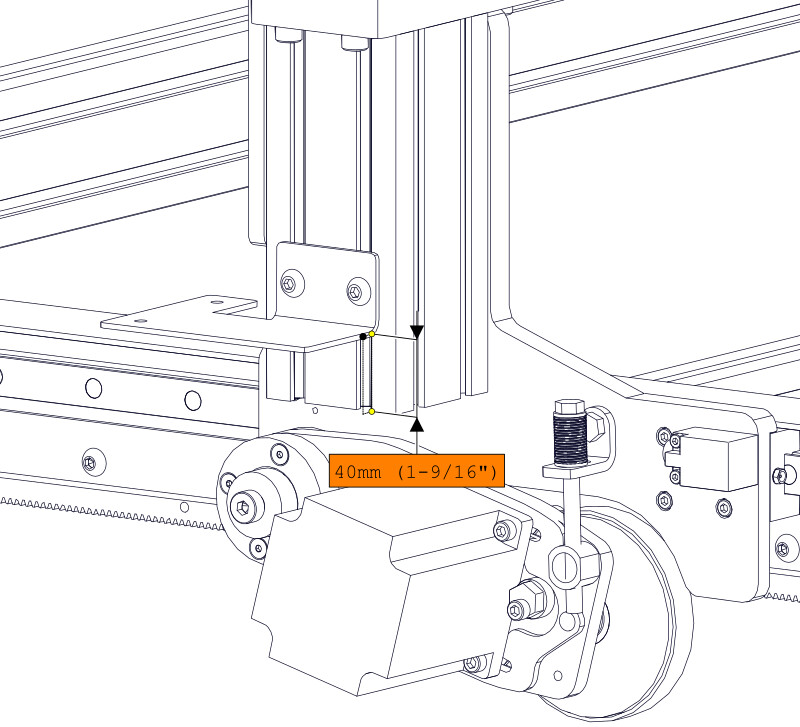
7.1.2.3

- Position the riser cable track bracket flush with the bottom of the riser extrusion.
- Fully tighten the fastener.
7.1.2.4
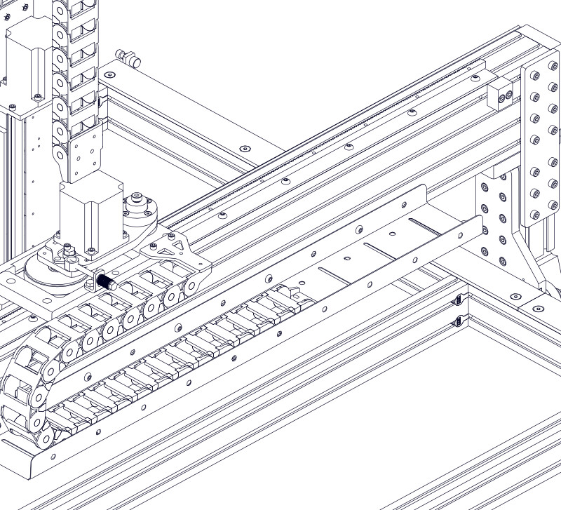
- Place the 75mm Cable Track Section E into the cable track tray, oriented with the fixed end at the front of the tray.
Assembly Note
To determine which cable track section to use, measure the width. The 75mm cable track section is approximately 75mm (3") wide.
The fixed end of the cable track section is the one that does not rotate independently.
7.1.2.4
- Attach the cable track section to the riser cable track bracket using M6 x 12mm Flat Head Screws H and M6 Hex Jam Nuts J .
Assembly Note
The other end of the cable track section will be attached after electronics installation.
7.2 - Z Axis Cable Track
Parts List
| ID | QTY | Part/Description | Package Label |
|---|---|---|---|
A | Z-Axis Cable Track Bracket, Back CRP150-10 Z-Axis Cable Track Kit | ||
B | Z-Axis Cable Track Bracket, Front CRP150-13 Z-Axis Cable Track Kit | ||
C | 50mm Cable Track Section (18 links) Z-Axis Cable Track Kit | ||
Z-Axis Cable Track Fasteners CT-Z-PRO-FAST-21.1 Z-Axis Cable Track Kit | |||
D | M6 x 12mm Flat Head Screw (4 per bag) CT-Z-PRO-FAST-21.1Packaged in | ||
E | M8 x 16mm Socket Head Cap Screw (2 per bag) CT-Z-PRO-FAST-21.1Packaged in | ||
F | M8 x 12mm Button Head Cap Screw (4 per bag) CT-Z-PRO-FAST-21.1Packaged in | ||
G | M8 Roll-in T-Nut (6 per bag) CT-Z-PRO-FAST-21.1Packaged in |
Tools List
| Requirement | Tool |
|---|---|
| Required | 4mm Allen Wrench |
| Required | 6mm Allen Wrench | Required | Tape Measure |
7.2.1 - Cable Track Installation
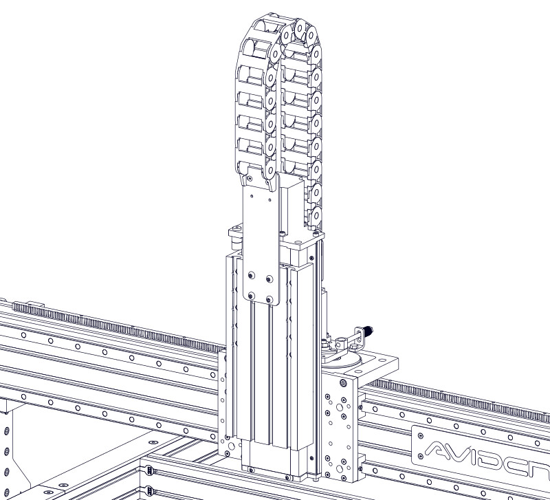
7.2.1.1
- Attach the Z Axis Cable Track Bracket, Back A to the free end of the 50mm Cable Track Section (18 links) C using M6 x 12mm Flat Head Screws D .
Assembly Note
The free end of the cable track section is the one that can rotate independently.
Assembly Note
To differentiate between the 50mm cable track section used on the Z axis versus the gantry, note the orientation of the cable track ends in the image.
7.2.1.2
- Attach the Z axis cable track bracket to the back of the Z axis using M8 x 16mm Socket Head Cap Screws D and M8 Roll-in T-Nuts G .
- Partially tighten the fasteners.
Assembly Note
When installing the T-Nuts, take care to prevent them from sliding down the T-Slot.
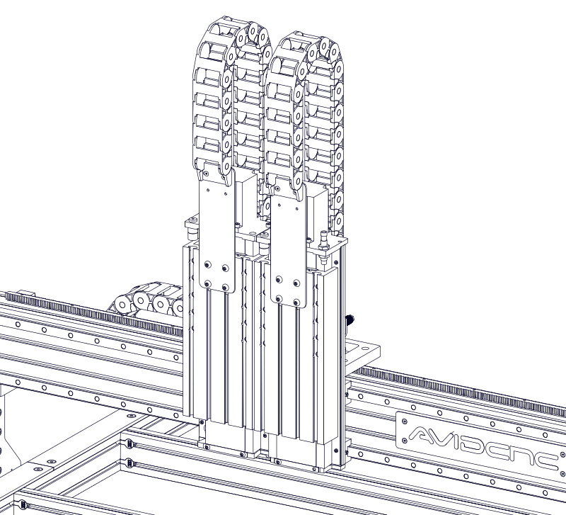
Assembly Note
Images only show one Z axis, but cable track installation will be repeated on the second Z axis.
7.2.1.3

- Position the bracket 25mm (1") from the top of the Z axis, as indicated.
- Fully tighten the fasteners.
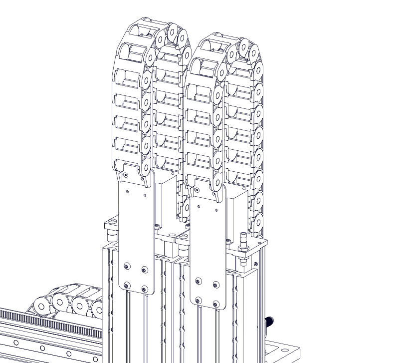
7.2.1.4
- Partially thread M8 x 12mm Button Head Cap Screws F onto M8 Roll-in T-Nuts G , through the Z Axis Cable Track Bracket, Front B .
7.2.1.5
- Slide the assembled Z axis cable track bracket into the middle two T-Slots of the Z axis moving plate.
- Partially tighten the fasteners.
7.2.1.6

- Position the bracket 75mm (3") from the top of the Z axis moving plate, as indicated.
- Fully tighten the fasteners.
Assembly Note
If you need to minimize the overall height of your CNC machine, this bracket can be installed lower on the Z axis moving plate. This dimension will be determined based on the mounting position of your spindle.
7.2.1.7
- Attach the cable track section to the bracket using M6 x 12mm Flat Head Screws D .
- Repeat this process to install the Z axis cable track on the second Z axis.
7.3 - Gantry Cable Track
Parts list
| ID | QTY | Part/Description | Package Label |
|---|---|---|---|
A | 1 | Gantry Cable Track Bracket CRP150-09 | Cable Track Base Kit |
B | 1 2 | Cable Track Tray QT40x125B | Cable Track Base Kit |
C | 1 | Cable Track Tray (short) QT40x125BS | Cable Track Base Kit |
D | 1 | 50mm Cable Track Section | Cable Track Base Kit |
1 | Cable Track Base Fasteners CT-PRO-FAST-20.2 | Cable Track Base Kit | |
E | 2 | M6 x 12mm Socket Head Cap Screw | CT-PRO-FAST-20.2Packaged in |
F | 2 | M6 x 12mm Flat Head Screw | CT-PRO-FAST-20.2Packaged in |
Gantry Cable Tray Fasteners CT-TRAY-GANTRY-PRO-FAST-20.2 | Cable Track Base Kit | ||
I | M8 x 12mm Button Head Cap Screw M8 x 12mm Button Head Cap Screw (5 per bag) | CT-TRAY-GANTRY-PRO-FAST-20.2Packaged in | |
J | M8 Roll-in T-Nut M8 Roll-in T-Nut (5 per bag) | CT-TRAY-GANTRY-PRO-FAST-20.2Packaged in | |
| Remaining parts from CT-PRO-FAST-20.2 used in future section | |||
Tools List
| Requirement | Tool |
|---|---|
| Required | 4mm Allen Wrench |
| Required | 5mm Allen Wrench |
| Required | Adjustable Wrench |
| Required | Tape Measure |
7.3.1 - Cable Track Tray Installation
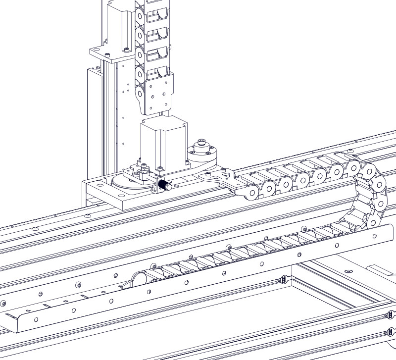
7.3.1.1
- Attach the Gantry Cable Track Bracket A to the gantry R&P plate using M6 x 12mm Socket Head Cap Screws E .
7.3.1.2
- Attach a Cable Track Tray (short) C to the bottom T-Slot on the gantry extrusion using M8 x 12mm Button Head Cap Screws I and M8 Roll-in T-Nuts J .
- Attach a Cable Track Tray B to the bottom T-Slot on the gantry extrusion using M8 x 12mm Button Head Cap Screws I and M8 Roll-in T-Nuts J .
- Partially tighten the fasteners.
7.3.1.3
- Attach a Cable Track Tray B to the bottom T-Slot on the gantry extrusion using M8 x 12mm Button Head Cap Screws I and M8 Roll-in T-Nuts J .
- Partially tighten the fasteners.
- Repeat the previous step to install a second cable track tray.
7.3.1.4


- Center the cable track trays between the ends of the gantry and fully tighten the fasteners.
7.3.2 - Cable Track Installation
7.3.2.1
- Place the 50mm Cable Track Section D into the cable track tray, oriented with the fixed end on the bottom.
Assembly Note
The fixed end of the cable track section is the one that does not rotate independently.
Alternate Cable Track Location
If locating the table cable track on the left side of the machine, orient the cable track section so the cables exit the cable track towards the left side of the machine.
7.3.2.2
- Attach the cable track section to the gantry cable track bracket using M6 x 12mm Flat Head Screws F .
Assembly Note
The other end of the cable track section will be attached after electronics installation.