8. Accessories


Dual-Use Machines
Images in this section show a machine with a single Z axis. It is highly recommended to install your routing tool on the left Z axis (when looking from the front of the machine), which will correspond with the electronics installation in the next section.
Dual-Use Machines
Images in this section show a machine with a single Z axis. It is highly recommended to install your primary routing tool on the left Z axis (when looking from the front of the machine), which will correspond with the electronics installation in the next section.


| ID | QTY | Part/Description | Package Label |
|---|---|---|---|
A | 1 | 3 HP Avid CNC Spindle | Spindle Kit |
A | 1 | 4 HP Avid CNC Spindle | Spindle Kit |
A | 1 | 8.7 HP Avid CNC Spindle | Spindle Kit |
A | 1 | AV70S Spindle | Spindle Kit |
A | 1 | AV40S Spindle | Spindle Kit |
1 | Spindle Tramming Hardware CRP144-00-SPINDLE-TRAM-21.1 CRP144-00-21-TRAM-21.2 | Spares & Accessories Bundle | |
B | 1 | Base Adapter CRP144-33 Base Adapter CRP144-23 | Spindle Tramming Hardware |
C | 1 | Tramming Plate CRP144-21 | Spindle Tramming Hardware |
1 | Mounting Base Adapter Fasteners CRP144-03-FAST-SPINDLE-21.1 | Spindle Tramming Hardware | |
D | 10 4 | M8 x 16mm Socket Head Cap Screw | |
E | 4 | M6 x 16mm Socket Head Cap Screw | |
F | 4 | M8 Roll-in T-Nut | |
1 | Mounting EZ-Tram Fasteners CRP144-21-FAST-21.2 | Spindle Tramming Hardware | |
G | 1 | Eccentric Bushing B3X-HIT | |
H | 1 | M8 Shoulder Bolt - 10mm x 16mm | |
I | 1 2 | M8 x 30mm Socket Head Cap Screw | |
J | 1 | M8 x 35mm Socket Head Cap Screw | |
1 | Mounting Fasteners CRP5530-00-FAST | Spindle Accessories | |
K | 1 | M8 x 30mm Hex Cap Screw | |
L | 6 | M8 x 20mm Socket Head Cap Screw | |
| Remaining parts from CRP144-03-FAST-SPINDLE-21.1 are not used Remaining parts from CRP5530-00-FAST are not used | |||
Tools List
| Requirement | Tool |
|---|---|
| Required | 5mm Allen Wrench |
| Required | 6mm Allen Wrench |
| Required | Adjustable Wrench |
| Required | Tape Measure |
| Required | 13mm Open End or Box Wrench |
| Recommended | 13mm Ratcheting Box Wrench |
| Recommended | Torque Wrench (up to 15 ft-lb / 20 Nm) |
| Recommended | 6mm Hex Bit for Torque Wrench |
8.1.1 - Installation Overview
The design of our Ballscrew Z-Axis Moving Plate allows the spindle mount to be located at various heights to fit your particular application. The instructions specify a mounting height that will be applicable in most use cases. The figures below show the vertical range of an example tool using this mounting location.
Note
4 HP Hiteco spindle shown. Your spindle may look different.
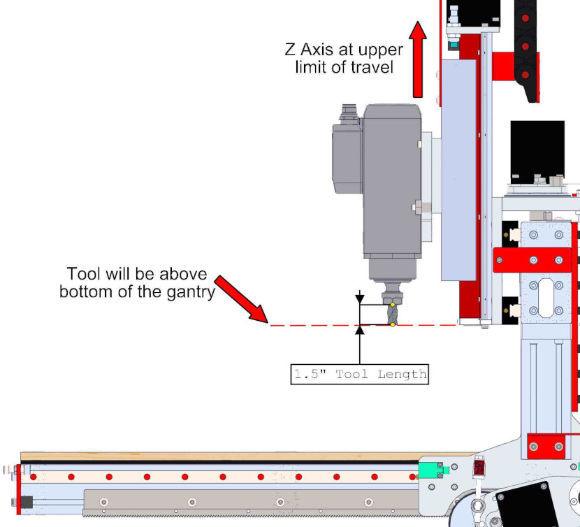
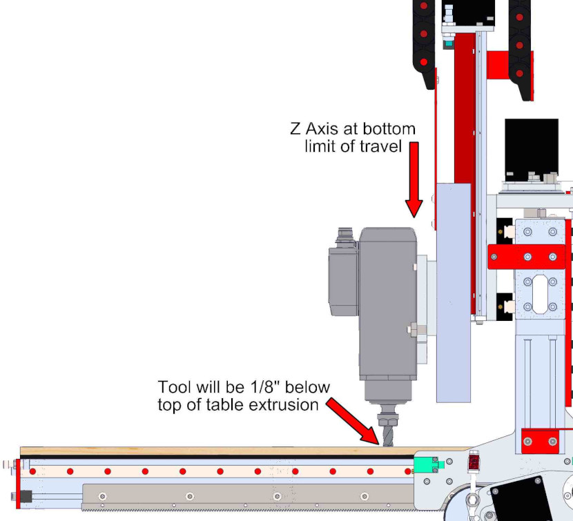
The examples above applies for a PRO CNC machine configured with an 8" Z-Axis and 8" Gantry Height, using a tool with a length of 1.5". If you are using a different machine configuration or tool length, you will need to adjust your router or spindle mount location accordingly.
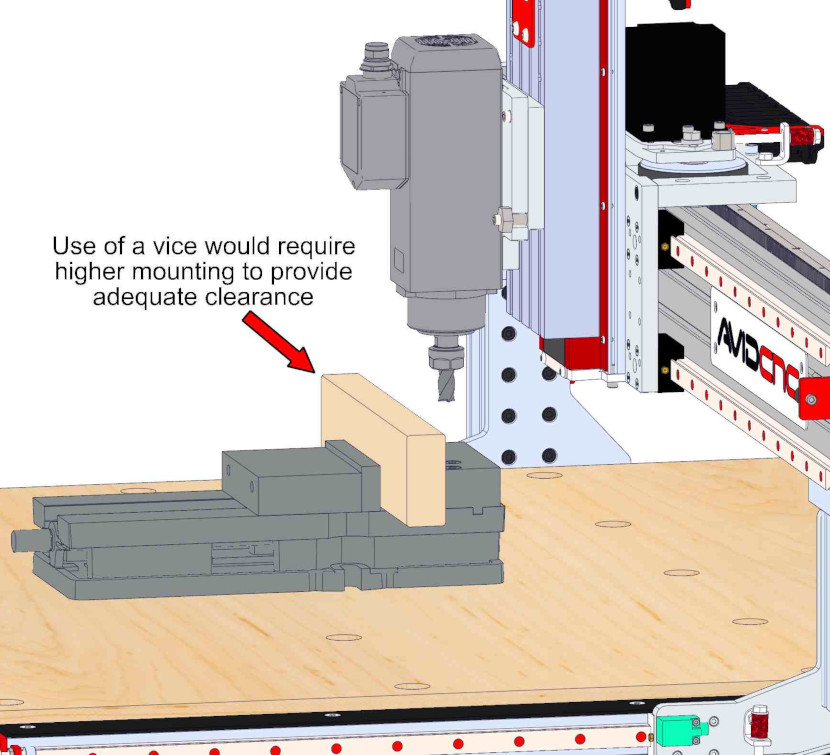
Many situations will require a different mounting location than the one specified in these instructions. For example if a vise is used to hold work pieces, a higher mounting position may be required.
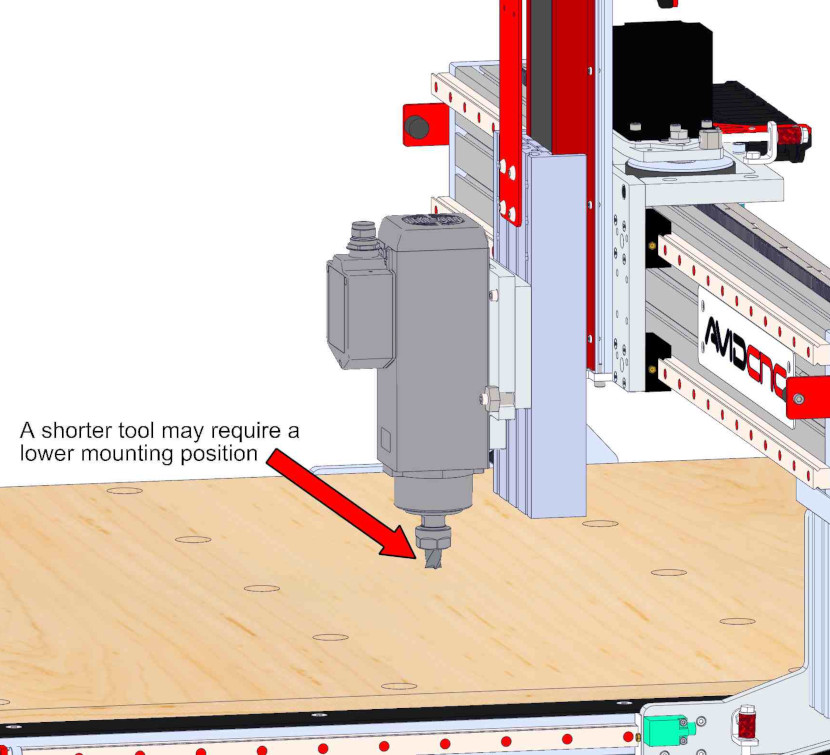
If shorter tools are commonly used, it may be necessary to position the router or spindle in a lower position.
Whatever mounting position you choose, it is recommended to mount the base adapter/tramming plate in the highest position possible while still allowing the vertical range required.
8.1.2 - Base Adapter
8.1.2.1
- Insert M8 x 30mm Hex Cap Screw K into hole as shown prior to installing Base Adapter B on the spindle. This screw will be used in a later step.
8.1.2.2
- Attach the Base Adapter B to the AV70SAV40S Spindle A using M8 x 20mm Socket Head Cap Screws L .
- Fully tighten M8 fasteners to 13-15 ft-lb (17-20 Nm).
Assembly Note
Do not overtighten the fasteners or you may cause damage to the spindle body.
- Attach the Base Adapter B to the 3 HP Avid CNC Spindle A using M8 x 16mm Socket Head Cap Screws D .
- Attach the Base Adapter B to the 4 HP Avid CNC Spindle A using M6 x 16mm Socket Head Cap Screws E .
- Fully tighten the fasteners.
Assembly Note
Use the upperlower set of mounting holes on the spindle. Do not overtighten the fasteners or you may cause damage to the spindle body.
8.1.3 - Tramming Mount
8.1.3.1
- Partially thread M8 x 16mm Socket Head Cap Screws D onto M8 Roll-in T-Nuts F , through the Tramming Plate C .
Assembly Note
Orient the tramming plate with the dowels on the same side at the T-Nuts.
8.1.3.2
- Slide the assembled tramming plate into the middle two T-Slots on the Z Axis.
8.1.3.3

- Position the tramming plate 89mm (3-1/2")96mm (3-3/4") from the bottom of the Z Axis moving plate, as shown.
- Partially tighten the fasteners.
8.1.3.4

- While applying pressure on the tramming plate in the indicated direction, fully tighten the fasteners.
8.1.3.5
- Install the base adapter (that's attached to the spindle) onto the tramming plate using an M8 Shoulder Bolt H , M8 x 30mm Socket Head Cap Screws I , M8 x 30mm Hex Cap Screw K previously inserted through base adapter and M8 x 35mm Socket Head Cap Screw J (installed through the Eccentric Bushing G).
- Fully tighten the fasteners.
Assembly Note
The spindle is hidden for illustrative purposes.
8.1.3.6


- Following the assembly of your machine, our Tramming Instructions show how to make test cuts to determine if the tram needs to be adjusted. If so, slightly loosen all four mounting fasteners (those installed in the previous step) and rotate the eccentric bushing. Re-tighten the fasteners after adjusting the tram.
8.2 - Spindle Air Connections
Parts List
| ID | QTY | Part/Description | Packaged In |
|---|---|---|---|
1 | Spindle Air Preparation Kit | ||
A | 1 | Assembled Air Regulator | Spindle Air Preparation Kit |
B | 2 | M6 x 12mm Socket Head Cap Screw | Spindle Air Preparation Kit |
C | 2 | M6 Roll-in T-nut | Spindle Air Preparation Kit |
D | 1 | 6mm Hose | Spindle Air Preparation Kit |
E | 1 | 8mm to 6mm Wye Fitting | Spindle Air Preparation Kit |
Tools List
| Requirement | Tool |
|---|---|
| Required | 5mm Allen Wrench |
| Required | Wire Snips, Scissors or Utility Knife (for cutting hose) |
8.2.1 - Install Air Regulator
8.2.1.1
- Install the Air Regulator A on the inside front face of the electronics bar using M6 x 12mm Socket Head Cap Screws B and M6 Roll-in T-nuts C.
Assembly Note
The air regulator mounting location shown is the default location. The regulator may be located elsewhere for covenience.
8.2.2 - Prepare Spindle Air Connection
8.2.2.1
- Cut the 6mm Hose D (shorter segment) into two equal lengths.
- Insert the two pieces of 6mm Hose D into the fittings on the top of the box located at the front of the spindle motor.
- Insert the free ends of the hose segments into the 8mm to 6mm Wye Fitting E.
Assembly Note
The final spindle air connection will be made during cable routing through the cable track in a later step.
8.3 - Tool Tightening Fixture
Parts List
| ID | QTY | Part/Description | Packaged In |
|---|---|---|---|
1 | ISO30 Tightening Fixture Kit | CRP5531-00-01 | |
A | 2 | M8 Roll-in T-nut | ISO30 Tightening Fixture Kit |
B | 2 | M8 x 25mm Socket Head Cap Screw | ISO30 Tightening Fixture Kit |
C | 1 | Tool Tightening Fixture Base Assembly | ISO30 Tightening Fixture Kit |
Tools List
| Requirement | Tool |
|---|---|
| Required | 6mm Allen Wrench |
8.3.1 - Install Tool Tightening Fixture
8.3.1.1
- Insert M8 Roll-in T-nuts A in the slot on the bottom of the front table crossmember, or other convenient location.
- Use M8 x 25mm Socket Head Cap Screws B to attach the Tool Tightening Fixture Base Assembly C to the machine frame.
8.2 - Router Installation

Parts List
| ID | QTY | Part/Description | Package Label |
|---|---|---|---|
A | 1 | Router Mount CRP144-XX | Spindle Kit |
B | 1 | Base Adapter CRP144-33 | Spindle Kit |
1 | CRP144-03-FAST-ROUTER | Spindle Kit | |
C | 4 | M8 x 16mm Socket Head Cap Screw | |
D | 4 | M5 x 20mm Socket Head Cap Screw | |
E | 4 | M8 Roll-in T-Nut | |
F | 1 | Tramming Plate CRP144-21 (optional) | Spindle Kit |
1 | CRP144-21-FAST-21.2 (optional) | Spindle Kit | |
G | 1 | B3X-HIT Eccentric Bushing (optional) | |
H | 1 | M8 Shoulder Bolt - 10mm x 16mm (optional) | |
I | 2 | M8 x 30mm Socket Head Cap Screw (optional) | |
J | 1 | M8 x 35mm Socket Head Cap Screw (optional) | |
| Optional parts included when router mount purchased with tramming adapter | |||
Tools List
| Requirement | Tool |
|---|---|
| Required | 4mm Allen Wrench |
| Required | 5mm Allen Wrench |
| Required | 6mm Allen Wrench |
| Required | Adjustable Wrench |
| Required | Tape Measure |
8.2.1 - Installation Overview
The design of our Ballscrew Z-Axis Moving Plate allows the router mount to be located at various heights to fit your particular application. The instructions specify a mounting height that will be applicable in most use cases. The figures below show the vertical range of an example tool using this mounting location.
The examples above applies for a PRO CNC machine configured with an 8" Z-Axis and 8" Gantry Height, using a tool with a length of 1.5". If you are using a different machine configuration or tool length, you will need to adjust your router or spindle mount location accordingly.
Many situations will require a different mounting location than the one specified in these instructions. For example if a vise is used to hold work pieces, a higher mounting position may be required.
If shorter tools are commonly used, it may be necessary to position the router or spindle in a lower position.
Whatever mounting position you choose, it is recommended to mount the base adapter/tramming plate in the highest position possible while still allowing the vertical range required.
8.2.2 - Base Adapter
8.2.2.1
- Attach the Router Mount A to the Base Adapter B using M5 x 20mm Socket Head Cap Screws D .
8.2.2.2
Configuration Option
If you purchased the optional tramming adapter, skip to the Tramming Mount section.
- Partially thread M8 x 16mm Socket Head Cap Screws C onto M8 Roll-in T-Nuts E , through the base adapter.
8.2.2.3
- Slide the router mount assembly into the middle two T-Slots on the Z Axis.
8.2.2.4

- Position the base adapter 25mm (1") from the bottom of the Z Axis moving plate, as shown.
- Fully tighten the fasteners.
8.2.2.5
- Slide the Router K into the router mount.
8.2.2.6
- Install the 1/4" x 1" Socket Head Cap Screw L clamping fasteners and fully tighten.
8.2.3 - Tramming Mount
Configuration Option
The remaining steps are only applicable if you purchased the optional tramming adapter.
8.2.3.1
- Partially thread M8 x 16mm Socket Head Cap Screws C onto M8 Roll-in T-Nuts E , through the Tramming Plate F .
Assembly Note
Orient the tramming plate with the dowels on the same side at the T-Nuts.
8.2.3.2
- Slide the assembled tramming plate into the middle two T-Slots on the Z Axis.
8.2.3.3

- Position the tramming plate 46mm (1-13/16") from the bottom of the Z Axis moving plate, as shown.
- Partially tighten the fasteners.
8.2.3.4
- While applying pressure on the tramming plate in the indicated direction, fully tighten the fasteners.
8.2.3.5
- Install the assembled base adapter onto the tramming plate using an M8 Shoulder Bolt H , M8 x 30mm Socket Head Cap Screws I , and M8 x 35mm Socket Head Cap Screw J (installed through the Eccentric Bushing G).
- Fully tighten the fasteners.
8.2.3.6
- Slide the Router K into the router mount.
8.2.3.7
- Install the 1/4" x 1" Socket Head Cap Screw L clamping fasteners and fully tighten.
8.2.3.8

- Following the assembly of your machine, our Tramming Instructions show how to make test cuts to determine if the tram needs to be adjusted. If so, slightly loosen all four mounting fasteners (those installed in the previous step) and rotate the eccentric bushing. Re-tighten the fasteners after adjusting the tram.

| ID | QTY | Part/Description | Package Label |
|---|---|---|---|
A | 1 | Torch Mount Base CRP145-06 | CRP145-00-19.2 |
B | 1 | Torch Mount CRP145-00 | CRP145-00-19.2 |
1 | CRP145-00-FAST | CRP145-00-19.2 | |
C | 4 | M8 x 16mm Socket Head Cap Screw | |
D | 4 | M8 Roll-in T-Nut | |
E | 1 | M5 x 16mm Socket Head Cap Screw | |
Tools List
| Requirement | Tool |
|---|---|
| Required | 6mm Allen Wrench |
| Required | Tape Measure |
8.3.1 - Torch Mount Installation
8.3.1.1
- Partially thread M8 x 16mm Socket Head Cap Screws C onto M8 Roll-in T-Nuts D , through the Torch Mount Base A .
8.3.1.2
- Slide the assembled torch mount base into the middle two T-Slots on the Z Axis.
8.3.1.3

- Position the torch mount base 100mm (4") from the bottom of the Z Axis moving plate.
- Fully tighten the fasteners.
8.3.1.4
- Attach the Torch Mount B to the torch mount base (the torch mount is magnetically attached, no fasteners are required).
Assembly Note
The wiring attached to the torch mount will be routed in the next section (Electronics).
8.4 - Plasma Water Table

Water Table Sizes
The images and part quantities in this section may not be applicable for your specific size of water table, however all instructions procedures are identical.
Parts List
| ID | QTY | Part/Description | Package Label | ||||||||
|---|---|---|---|---|---|---|---|---|---|---|---|
A | 1 | Water Table * CRP511-4824-BASE Water Table * CRP511-4896-BASE Water Table * CRP511-4848-BASE | Water Table Crate | ||||||||
B | 6 24 12 | Water Table Slat * CRP511-03-50 | Water Table Crate | ||||||||
C | 1 | Water Table Bracket (Left) CRP511-05L | Water Table Crate | ||||||||
D | 1 | Water Table Bracket (Right) CRP511-05R | Water Table Crate | ||||||||
E | 1 | Water Table Drain Valve | Water Table Crate | ||||||||
1 | CRP511-00-FAST-22.1 | Water Table Crate | |||||||||
F | 1 | Water Table Drain Valve Gasket | | ||||||||
G | 8 | M8 x 12mm Socket Head Cap Screw | | ||||||||
H | 4 | M8 Roll-in T-Nut | | ||||||||
I | 2 | 7/16-14 x 1-1/2" Hex Cap Bolt | | ||||||||
J | 2 | 7/16-14 Hex Nut | | ||||||||
K | 2 | Rubber Washer | | ||||||||
L | 2 | Steel Washer | | ||||||||
1 | CRP511-4824-SPACER * CRP511-4896-SPACER * CRP511-4848-SPACER * | Water Table Crate | |||||||||
M | 18 72 36 | Aluminum Spacer * | | ||||||||
N | 18 72 36 | M8 x 30mm Socket Head Cap Screw * | | ||||||||
O | 18 72 36 | M8 Roll-in T-Nut * | | ||||||||
| * Parts shown for 4' x 4' water table. Quantities and part names may differ for other sizes. | * Parts shown for 4' x 2' water table. Quantities and part names may differ for other sizes. | * Parts shown for 4' x 8' water table. Quantities and part names may differ for other sizes. | |||||||||
A | 1 | CRP511-60120-BASE Water Table * Water Table * CRP511-6060-BASE | Water Table Crate | ||||||||
B | 30 15 | Water Table Slat * CRP511-03-62 | Water Table Crate | ||||||||
C | 1 | Water Table Bracket (Left) CRP511-05L | Water Table Crate | ||||||||
D | 1 | Water Table Bracket (Right) CRP511-05R | Water Table Crate | ||||||||
E | 1 | Water Table Drain Valve | Water Table Crate | ||||||||
F | 1 | Water Table Drain Valve Gasket | Water Table Crate | ||||||||
1 | CRP511-00-FAST-22.1 | Water Table Crate | |||||||||
G | 8 | M8 x 12mm Socket Head Cap Screw | | ||||||||
H | 4 | M8 Roll-in T-Nut | | ||||||||
I | 4 | 1/2" Flat Washer | | ||||||||
1 | CRP511-60120-SPACER * CRP511-6060-SPACER * | Water Table Crate | |||||||||
J | 90 45 | Aluminum Spacer * | | ||||||||
K | 90 45 | M8 x 30mm Socket Head Cap Screw * | | ||||||||
L | 90 45 | M8 Roll-in T-Nut * | | ||||||||
| * Parts shown for 5' x 5' water table. Quantities and part names may differ for other sizes. | * Parts shown for 5' x 10' water table. Quantities and part names may differ for other sizes. | ||||||||||
Tools List
| Requirement | Tool |
|---|---|
| Required | 6mm Allen Wrench |
| Required | Adjustable Wrench |
| Required | Tape Measure |
8.4.1 - Water Table Installation
8.4.1.1
- Place the Water Table A onto the table crossmembers.
8.4.1.2
- At the front right-hand corner of the water table, attach the Water Table Bracket (Right) D using M8 x 12mm Socket Head Cap Screws G .
Assembly Note
Use the correct bracket (left vs right) with the lower holes biased towards the center of the machine.
8.4.1.3
- At the front left-hand corner of the water table, attach the Water Table Bracket (Left) C using M8 x 12mm Socket Head Cap Screws G .
8.4.1.4
- Behind both water table brackets, install two M8 Roll-in T-Nuts H into the crossmember extrusion.
8.4.1.5
- Attach the water table brackets to the extrusion using M8 x 12mm Socket Head Cap Screws G .
Assembly Note
The water table should be roughly centered between the sides of the table frame.
8.4.1 - Drain Valve Installation
8.4.2.1
-
Attach the Water Table Drain Valve E and Water Table Drain Valve Gasket F to the water table using the following parts:
- 7/16-14 x 1-1/2" Hex Cap Bolt I
- Rubber Washer K
- Steel Washer L
- 7/16-14 Hex Nut J
Assembly Note
- Rubber washers are included with kits shipped after January 25, 2022. For kits shipped prior to this, use steel washers on both sides.
- To avoid damaging the rubber seal washers, hold the bolt head stationary and turn the nuts while installing the drain valve.
8.4.3 - Slat Installation
8.4.3.1
- Install an Aluminum Spacer M into the water table t-slot using an M8 x 30mm Socket Head Cap Screw N and M8 Roll-in T-Nut O .
- Partially tighten the fastener.
8.4.3.2

- Repeat the previous step to install a spacer in the remaining two t-slots. Position the outer spacers 57mm (2-1/4"), and the center spacer 127mm (5"), from the front of the water table.
- Fully tighten the spacer fasteners.
8.4.3.3

- Install the remaining spacers, spaced center-to-center 100mm (3-15/16") apart.
8.4.3.4
- Bend a Water Table Slat B and install it between the front three spacers, using the spacers to maintain tension on the slat.
- Bend a Water Table Slat B and install it between the front three spacers, using the spacers to maintain tension on the slat.
Assembly Note
The picture in the next step can be used as a reference for how to maintain slat tension with the spacers.
8.4.3.5

- Repeat the previous step to install the remaining water table slats.
8.5 - Tool Height Setter

Parts List
| ID | QTY | Part/Description | Package Label |
|---|---|---|---|
A | 1 | Tramming Cam | CRP5230-00-HW |
B | 1 | Tool Height Setter Assembly | CRP5230-00-12 |
C | 1 | Tool Height Setter Cover | Part of Tool Setter Assembly |
D | 2 | M3 x 8mm Socket Head Cap Screw | Part of Tool Setter Assembly |
E | 5 | M3 x 8mm Socket Head Cap Screw | CRP5230-00-HW |
| One M8 x 12mm Socket Head Cap Screw from CRP5230-00-HW will not be used for this application | |||
Tools List
| Requirement | Tool |
|---|---|
| Required | 2.5mm Allen Wrench |
| Required | 3mm Allen Wrench |
| Recommended | Rail Setting Jig, GHH20-JIG |
8.5.1 - Tool Height Setter Installation
Section Note
The recommended installation location for the Tool Height Setter is the front left corner of the machine. This is the location shown in the instructions. If you install your Tool Height Setter on the front right corner, the installation procedure is the same.
8.5.1.1
- Insert the Tramming Cam A into the pocket on the Tool Height Setter Adapter Plate, previously installed.
- Install an M3 x 8mm E screw as shown.
8.5.1.2
- Remove the Cover C from the Tool Height Setter Assembly B by removing the M3 x 8mm screws D.
8.5.1.3
- Attach the Tool Height Setter Assembly B to the Adapter Plate using M3 x 8mm Screws E.
8.5.2 - Tool Height Setter Tramming
Section Note
Prior to tramming the Tool Height Setter, ensure that your machine table has been squared and leveled, and your spindle has been trammed.
8.5.2.1
- Loosen the four indicated screws to tram the Tool Height Setter in the x-axis direction.
8.5.2.2
- Set a reference block on top of the Tool Setter to extend the height of the touch surface. The block needs to have two parallel surfaces approximately 2" apart. We recommend using the Rail Setting Jig in the orientation shown.
- Remove the collet from the spindle.
- Slowly jog the spindle nose down to the reference block.
- Rotate the Tramming Cam until the touch surface of the Tool Height Setter is parallel to the spindle nose.
- Retighten the four screws previously loosened to lock the position.
8.5.2.3
Section Note
It is likely that your Tool Height Setter will not need tramming in this orientation. Only tram this direction if it is not parallel to your work surface.
- Loosen the screws noted to tram the Tool Height Setter in the y-axis direction.
8.5.2.4


- To move the tip of the plate UP, tighten the upper set screw. To move the tip of the plate DOWN, tighten the lower set screw. Only adjust one set screw so that only one set screw is tight against the bearing block.
- Retighten the four screws previously loosened to lock the position.
8.5.2.5
- Replace the cover and two removed screws.
- Your Tool Height Setter is now installed and trammed.