10. Machine Setup
10.1 - Final Assembly
Parts List
| ID | QTY | Part/Description | Package Label | ||||||||||||||||||||||||||||||||||||||
|---|---|---|---|---|---|---|---|---|---|---|---|---|---|---|---|---|---|---|---|---|---|---|---|---|---|---|---|---|---|---|---|---|---|---|---|---|---|---|---|---|---|
A | Linear Rail Hole Cover GHH20-COVERS | Base Table Kit |
10.1.1 - Linear Rail Hole Covers
10.1.1.1
- Install a Linear Rail Hole Cover A in each hole of the linear rails.
- Repeat this process for both the table and gantry linear rails.
Assembly Note
We recommend installing the linear rail hole covers after your machine is assembled and running.
10.2 - Next Steps
- EX Control System Technical Manual (https://www.avidcnc.com/support/instructions/electronics/ex/manual/)
- Basic use instructions, major component overview and safety mechanisms for the Avid CNC EX Controller.
- Spindle / VFD System Technical Manual (https://www.avidcnc.com/support/instructions/accessories/spindles/setup/)
- System requirements and initial setup information.
- CNC12 Software Setup & Usage Guide (https://www.avidcnc.com/support/instructions/software/)
- Guides for installation, setup, and usage of CNC12 controller software.
- Dust Collection (https://www.avidcnc.com/support/instructions/machineSetup/dustCollection)
- Information about dust collection solutions for your machine.
- Auto Z & Corner Finding Touch Plate [ Video ] (https://youtu.be/NzIdFVuaGQc)
- Use of our touch plate with CNC12 and your machine.
- Machine Gantry Squaring [Video]
- How to square both our stepper and servo driven CNC machines.
- Tool Height Setter [Video]
- How to use the Tool Height Setter to improve your workflow.
- Wireless CNC Control Pendant [Video]
- Features and functions of the wireless control pendant.
- Plasma Overview with Avid CNC EX Controller [Video]
- An overview and demonstration of plasma functionality and workflow.
- Rotary Axis (https://www.avidcnc.com/support/instructions/rotary/assembly/)
- Assembly and installation instructions for the Avid CNC rotary axis.
- Laser Kit (https://www.avidcnc.com/support/instructions/laser/laserAssembly/)
- Assembly instructions for the Avid CNC laser kit.
10.3 - Spoilboard
Parts List
| ID | QTY | Part/Description | Package Label | ||||||||||||||||||||||||||||||||||||||
|---|---|---|---|---|---|---|---|---|---|---|---|---|---|---|---|---|---|---|---|---|---|---|---|---|---|---|---|---|---|---|---|---|---|---|---|---|---|---|---|---|---|
A | 1 | Spoilboard (not included) | |||||||||||||||||||||||||||||||||||||||
1 | Base Table Kit | ||||||||||||||||||||||||||||||||||||||||
B | M8 x 16mm Button Head Cap Screw | Spoilboard Fastener KitPackaged in | |||||||||||||||||||||||||||||||||||||||
C | M8 Roll-in T-Nut | Spoilboard Fastener KitPackaged in |
Tools List
| Requirement | Tool |
|---|---|
| Required | 6mm Allen Wrench |
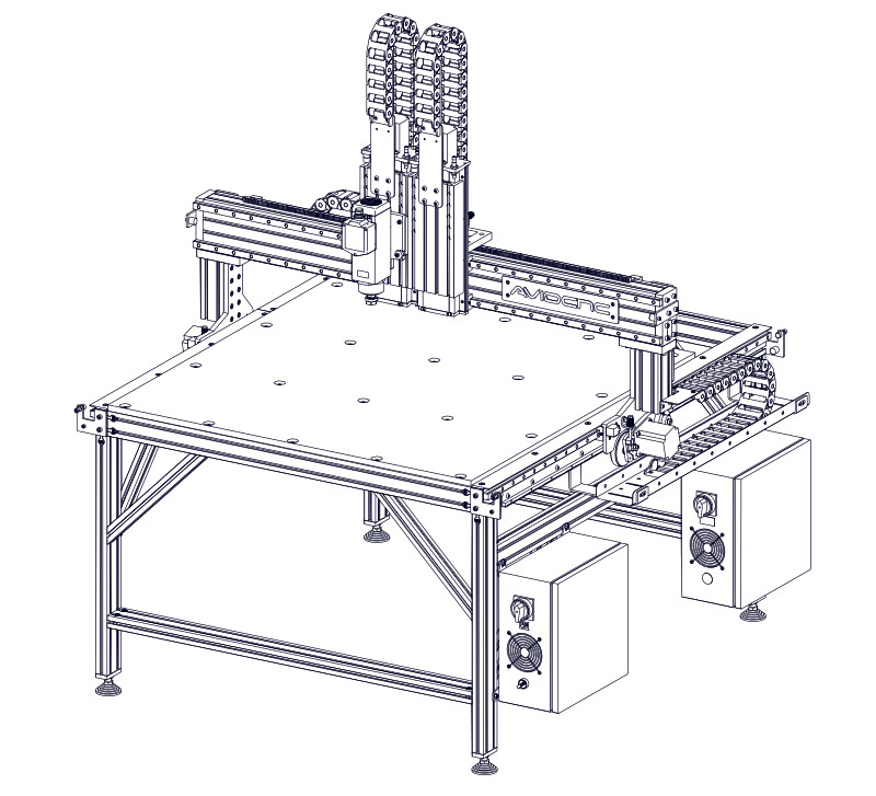
10.3.1 - Spoilboard Installation
10.3.1.1
- Attach the Spoilboard A to the table crossmembers using M8 x 16mm Button Head Cap Screws B and M8 Roll-in T-Nuts C .