System Settings
Indicator States
Servo Motors
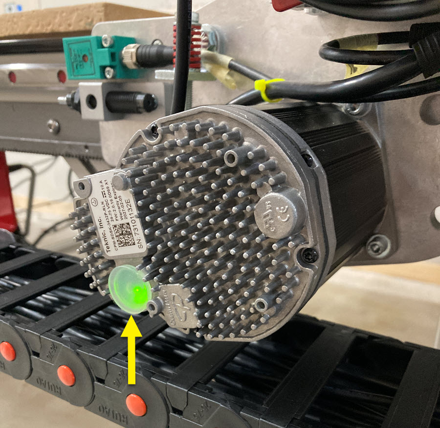
| LED Code | Meaning |
|---|---|
| Yellow (orange) flicker | Startup (performing commutation startup) This will show briefly when the motors are first powered. |
| Yellow (orange) solid | Motor disabled, but has power After powering up the EX controller the motors will be in this state. |
| Green flicker | Enabled Once any motor is jogged they should all be enabled. |
Servo Controller
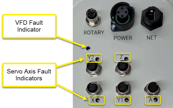
- There are LEDs on the gland plate for each axis and the VFD. Depending on the PCB revision these may be Red or Green, but the function is the same regardless of color.
- ON indicates the drive has no faults, OFF means that drive or VFD has a fault or is disconnected unexpectedly.
- The "A" LED will be on if that axis is not in use and jumper/DIP is set correctly.
Servo Board Settings
Servo Boards with DIP Switches
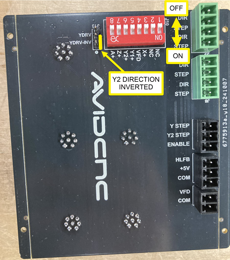
J13, Y2 Direction Select - This jumper reverses the direction signal for the Y2 motor so that Y1 and Y2 motors spin in opposite directions.
- Large Format (PRO CNC / Standard CNC): Jumper connected on YDRV-INV pins (towards "0")
- Benchtop (Benchtop PRO / Benchtop Standard): Jumper connected on YDRV pins (away from "0")
J10, DIP Switches - The DIP switches connect Drive Ready signals from each labeled motor or VFD to a combined High Level Feedback (HLFB) signal sent to the Acorn. DIP switches set to OFF (toward the number) connect the signal for a device. Switches set to ON (away from the number) exclude that device from the HLFB. To prevent false faults, any switch for an unused device should be turned ON.
Systems without A axis:
- SW8 = ON
- SW1 - SW7 = OFF
Systems with A axis:
- SW1 - SW8 = OFF
Servo Boards with Jumpers
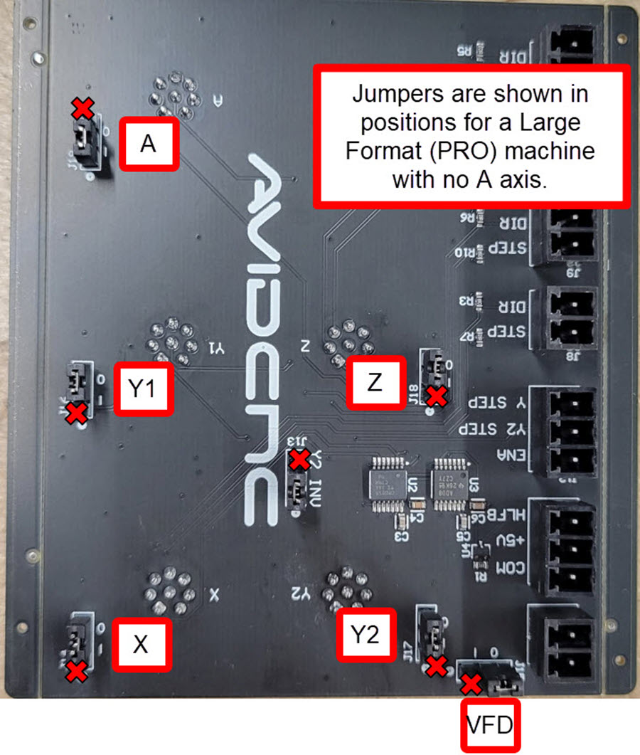
J13, Y2 INV - This jumper reverses the direction signal for the Y2 motor so that Y1 and Y2 motors spin in opposite directions.
- Large Format (PRO CNC / Standard CNC): Jumper connected to middle and "0" pins
- Benchtop (Benchtop PRO / Benchtop Standard): Jumper connected to middle and "J13" pins
Other Jumpers - All other jumpers are used to connect Drive Ready signals from a device to a combined High Level Feedback (HLFB) signal sent to the Acorn. The jumpers have two positions, "I" and "0". Jumpers set to "0" connect the Drive Ready signal for that device. Jumpers set to "I" exclude that device from the HLFB. To prevent false faults, any jumper for an unused device should be set to "I".
Systems without A axis:
- A jumper set to "I"
- All other jumpers set to "0"
Systems with A axis:
- All jumpers set to "0"
What are the other 'Y2 INV' jumpers?
There may be additional jumper positions labeled 'Y2 INV' present on other circuit boards intended for systems with stepper motors. These jumpers have no effect on your servo system.