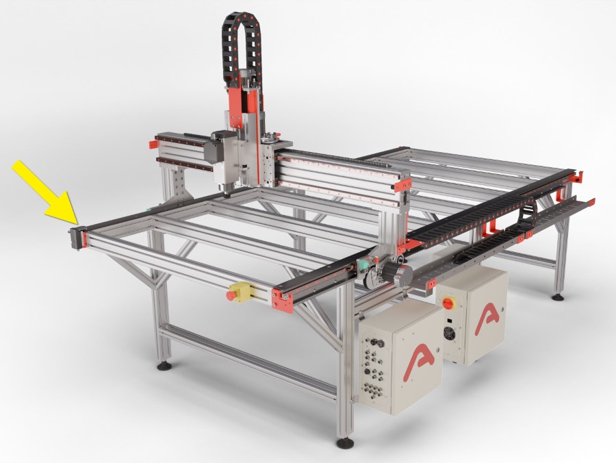
System Overview
EX Controller Components
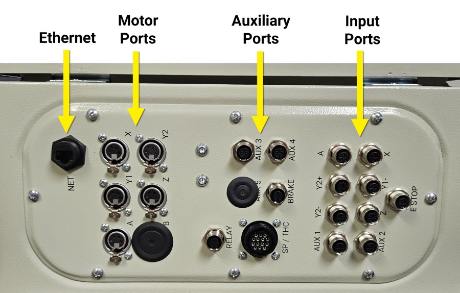
Note: Nema 34 motor connectors are shown. Connector locations and labeling are the same for Nema 23.
Plasma
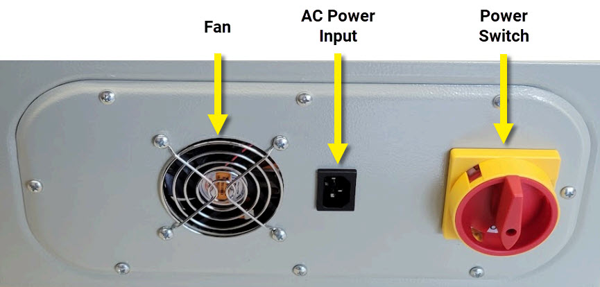
Emergency Stop
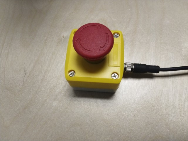
The emergency stop system is a normally closed circuit and must be plugged in for the CNC controller to operate. It is recommended to keep it within easy reach during machine operation so it is quickly accessible if the machine needs to be emergency stopped.
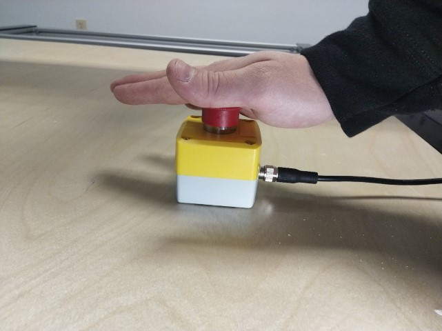
To activate the emergency stop, press down on the red button. The machine will come to a stop and all outputs connected to the CNC controller will be turned off. Motor power is removed.
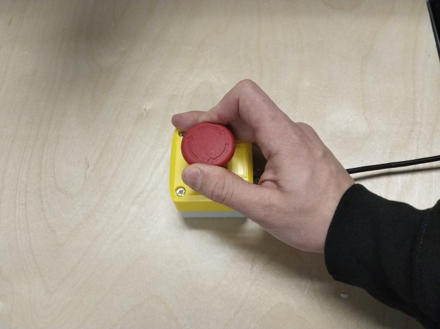
In order to clear the emergency stop, twist the red button clockwise until it releases.
Tool Height Setter
The Tool Height Setter is an integral part of the EX Control system. It provides a fixed reference height for tool lengths and work surface location.
For more information
- Usage instructions: CNC12 Operation Guide
System Identification
Serial Number
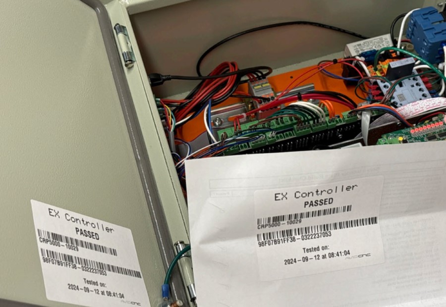
Each controller is labeled with a serial number starting in "CRP5000 - " after passing QC tests. The label is found on the inside of the enclosure lid.
Identifying Features
There are several major features that can differentiate controller versions.
Servo Motor vs Stepper Motor
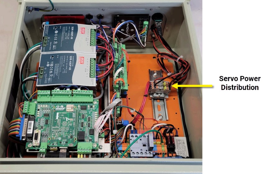
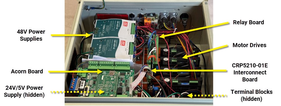
Servo motor systems do not have motor drives inside the enclosure. The drives are integrated on the motors. Terminal blocks take the place of motor drives in the enclosure.
Router vs Plasma
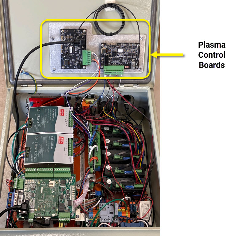
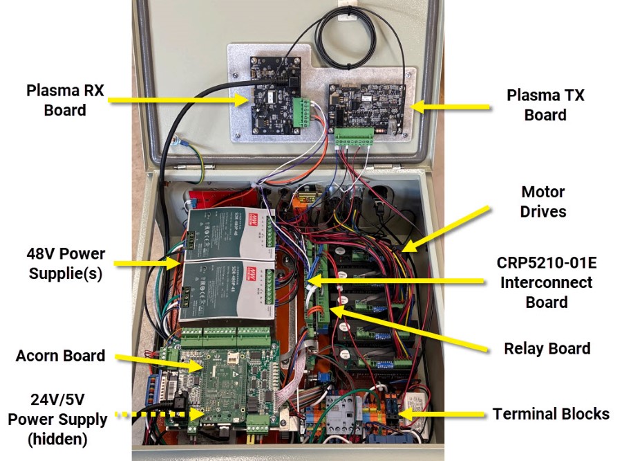
Plasma enabled systems have an extra set of control boards mounted to the enclosure lid.
5 Drive vs 4 Drive
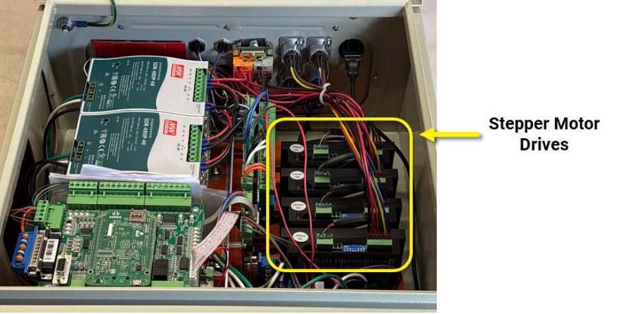
Systems with five motor drives will have five stepper motor drives in the enclosure.