EX Controller Stepper Retrofit - No Motor Change
Safety Note
Ensure your CNC control box is powered off with the power cable disconnected from the box.
Assembly Note
When upgrading to the EX Control System, you must reprogram your spindle fault parameter on your VFD. Please see the VFD Reprogramming Instructions for steps on reprogramming your VFD.
1. Gantry Bumper Shim Installation
Parts List
| ID | QTY | Part/Description | Package Label |
|---|---|---|---|
1 | Stepper Bumper Upgrade Kit | CPR815-00-STP-UP | |
B | 1 | Shim | |
C | 2 | M8 x 60mm Socket Head Cap Screw | |
Tools List
| Requirement | Tool |
|---|---|
| Required | 6mm Allen Wrench |
1.1 - Install Gantry Bumper Shim
Assembly Note
These instructions are for installing the Tool Height Setter at the front left corner of the machine, which is the recommended location. To locate the Tool Height Setter at the front right corner, install the Shim on the right side instead of the left.
1.1.1
- Remove the existing gantry bumper plate and bumper from the left side of the gantry.
1.1.2

- Re-install the Gantry Bumper Plate with attached bumper A and Shim B using the M8 x 60mm Socket Head Cap Screws C.
1.2 - Gantry Sensor Flag Adjustment

- Position the gantry sensor flags according to the table below, based on which side you installed your shim plate under the gantry bumper.
| Gantry Width | Flag | Shim Located on Left | Shim Located on Right |
|---|---|---|---|
| Standard | Left Sensor Flag | 28.5mm (1-1/8") | 38mm (1-1/2") |
| Standard | Right Sensor Flag | 38mm (1-1/2") | 28.5mm (1-1/8") |
| Extended | Left Sensor Flag | 9.5mm (3/8") | 0mm (0") |
| Extended | Right Sensor Flag | 0mm (0") | 9.5mm (3/8") |
2. Tool Height Setter
Parts List
| ID | QTY | Part/Description | Package Label |
|---|---|---|---|
1 | Stepper Bumper Upgrade Kit | CPR815-00-STP-UP | |
A | 1 | Tool Height Setter Adapter Plate | CRP5230-00-HW |
B | 2 | M8 x 25mm Socket Head Cap Screw | Stepper Bumper Upgrade Kit |
C | 1 | Tramming Cam | CRP5230-00-HW |
D | 1 | Tool Height Setter Assembly | CRP5230-00-12 |
E | 1 | Tool Height Setter Cover | Part of Tool Setter Assembly |
F | 2 | M3 x 8mm Socket Head Cap Screw | Part of Tool Setter Assembly |
G | 5 | M3 x 8mm Socket Head Cap Screw | CRP5230-00-HW |
| One M8 x 12mm Socket Head Cap Screw from CRP5230-00-HW will not be used for this application | |||
Tools List
| Requirement | Tool |
|---|---|
| Required | 2.5mm Allen Wrench |
| Required | 3mm Allen Wrench |
| Recommended | Rail Setting Jig, GHH20-JIG |
2.1 - Tool Height Setter Installation
2.1.1
- Remove the M8 x 20mm socket head cap screws from the existing bumper plate at the front left of the machine.
2.1.2

- During installation, bias the Tool Height Setter Adapter Plate toward the OUTSIDE of the machine, regardless of your chosen left (default) or right side mounting.
- The left/right bias of the Adapter Plate is chosen by using the corresponding mounting hole pair.
2.1.3

| Tool Setter Position | Height Above Crossmember |
|---|---|
| Low | 19.4mm (0.76") |
| Middle | 39.4mm (1.55") |
| High | 59.4mm (2.34") |
-
The Tool Height Setter can be mounted at several heights. Before mounting, consider your intended spoilboard and decide whether to mount the Tool Height Setter surface above or below the spoilboard surface.
- Above: Allows for easier tool measurement, particularly for tools > 3/4" (20mm) diameter, because there is no risk of the tool contacting the spoilboard. It does expose the Tool Height Setter to more risk of damage from loading material or cutting.
- Below: Protects the Tool Height Setter from more damaging situations. It is ideal if you need to fit wide workpieces or overrun the edges significantly with the cutter.
-
Mounting height may be adjusted as needed followed by recalibration of the Tool Height Setter. See CNC12 Routing Operation Guide for more information.
2.1.4

- At the same corner of the machine, install the Tool Height Setter Adapter Plate A on top of the existing bumper plate using the M8 x 25mm Socket Head Cap Screws B from the upgrade kit.
- The mounted height position (Low, Middle, High) from the previous table is chosen by using the corresponding Adapter Plate mounting hole pair.
2.1.5

- Insert the Tramming Cam C into the pocket on the Tool Height Setter Adapter Plate, previously installed.
- Install an M3 x 8mm G screw as shown.
2.1.6

- Remove the Cover E from the Tool Height Setter Assembly D by removing the M3 x 8mm screws F.
2.1.7

- Attach the Tool Height Setter Assembly D to the Adapter Plate using M3 x 8mm Screws G.
2.2 - Tool Height Setter Tramming
Section Note
Prior to tramming the Tool Height Setter, ensure that your machine table has been squared and leveled, and your spindle has been trammed.
2.2.1

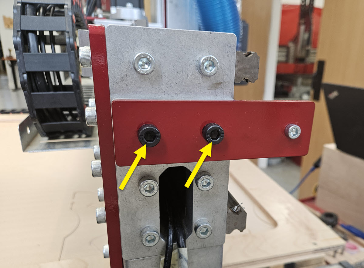
- Loosen the four indicated screws to tram the Tool Height Setter in the x-axis direction.
2.2.2

- Set a reference block on top of the Tool Setter to extend the height of the touch surface. The block needs to have two parallel surfaces approximately 2" apart. We recommend using the Rail Setting Jig in the orientation shown.
- Remove the collet from the spindle.
- Slowly jog the spindle nose down to the reference block.
- Rotate the Tramming Cam until the touch surface of the Tool Height Setter is parallel to the spindle nose.
- Retighten the four screws previously loosened to lock the position.
2.2.3
Section Note
It is likely that your Tool Height Setter will not need tramming in this orientation. Only tram this direction if it is not parallel to your work surface.

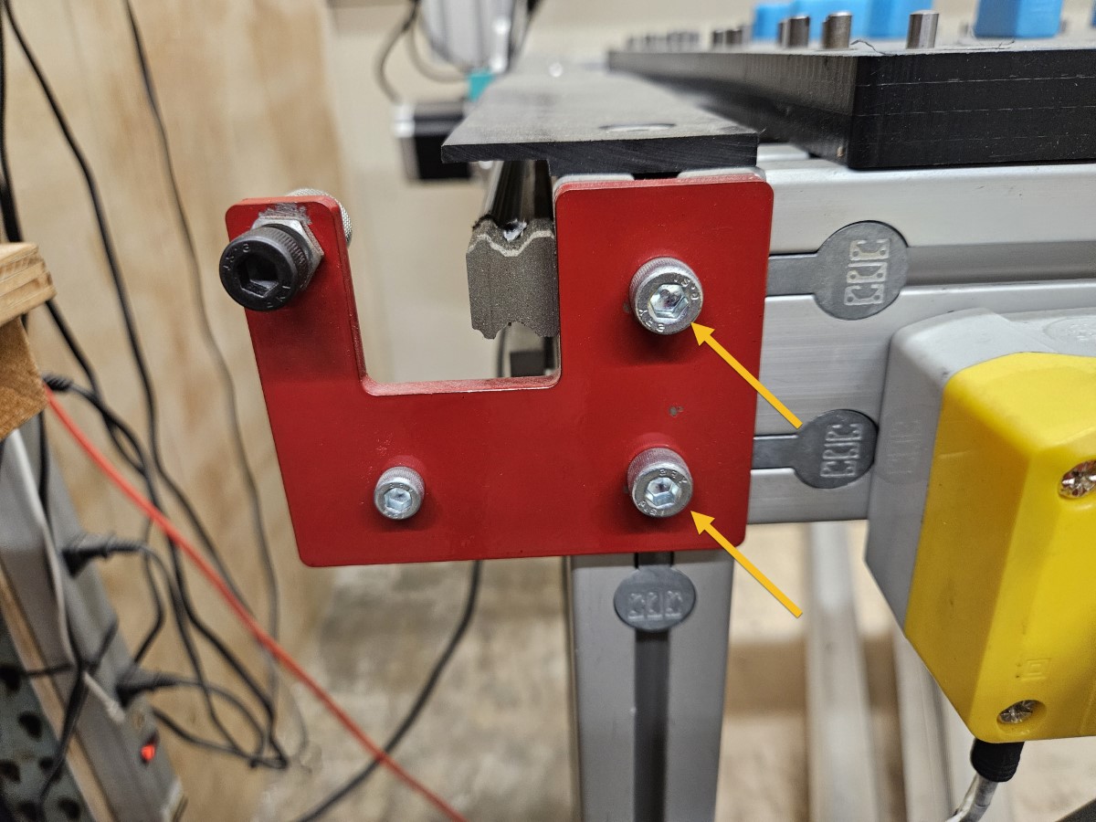
- Loosen the screws noted to tram the Tool Height Setter in the y-axis direction.
2.2.4


- To move the tip of the plate UP, tighten the upper set screw. To move the tip of the plate DOWN, tighten the lower set screw. Only adjust one set screw so that only one set screw is tight against the bearing block.
- Retighten the four screws previously loosened to lock the position.
2.2.5

- Replace the cover and two removed screws.
- Your Tool Height Setter is now installed and trammed.
3. Install EX Control Box
Parts List
| ID | QTY | Part/Description | Package Label |
|---|---|---|---|
1 | Key Hardware Bag | EX Controller Kit | |
A | 3 | M8 x 20mm Hex Bolt | Key Hardware Bag |
B | 3 | M8 Hex Nut | Key Hardware Bag |
C | 3 | Mounting Bracket | Key Hardware Bag |
Tools List
| Requirement | Tool |
|---|---|
| Required | 4mm Allen Wrench |
| Required | Adjustable Wrench |
| Required | Standard (Flat Tip) Screwdriver |
| Recommended | 13mm Combination Wrench |
3.1.1

- At the indicated locations, remove the plastic plugs from the EX Controller.
3.1.2

- At the locations with removed plugs, attach a Mounting Bracket C using M8 x 20mm Hex Bolts A and M8 Hex Nuts B .
3.1.3

- Remove the existing Plug and Play controller. Leave the T-nuts and set screws in the machine frame extrusion to be reused.
- Attach the EX Controller to the leg kit using existing M8 x 25mm Set Screws D , M8 Hex Flange Nuts E , and M8 Roll-in T-Nuts F .
4. Control Box Connections
Parts List
| ID | QTY | Part/Description | Package Label |
|---|---|---|---|
1 | EX Controller | EX Controller Kit | |
A | 1 | Emergency Stop Cable, 20' | Emergency Stop Kit |
B | 1 | Emergency Stop Switch | Emergency Stop Kit |
C | 1 | C13 Power Cable | EX Controller Kit |
D | 1 | Ethernet Cable, 10' | EX Controller Kit |
E | 1 | M12 Sensor Cable, 12' | Tool Height Setter Hardware |
4.1.1
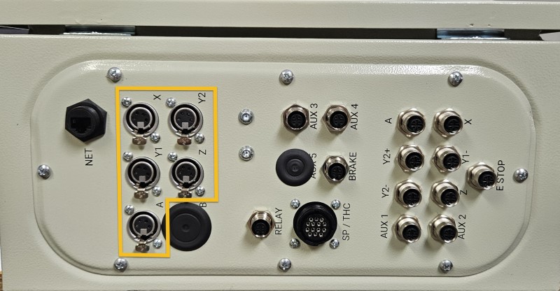
- Connect each motor cable to the appropriate motor port.
Assembly Note
The A motor port is used for either a CNC Rotary Axis, or the U axis (second Z axis) on a dual-use machine.
4.1.2
- Connect each sensor cable to the appropriate sensor port.
- Dual-use machines will need to use an M12 Sensor Cable Splitter to connect both the Z+ and U+ sensors to the Z sensor port.
Assembly Note
The A sensor port is used for the sensor on a CNC Rotary Axis.
4.1.3
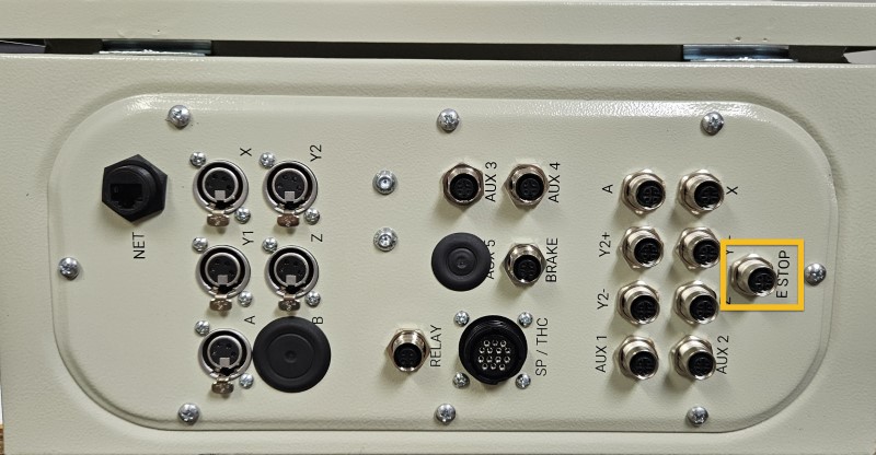
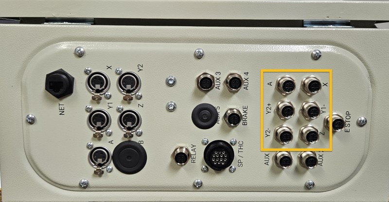
- Connect the Emergency Stop Cable, 20' A to the E Stop port.
- Connect the other end of this cable to the Emergency Stop Switch B .
4.1.4 - Spindle / Router Applications
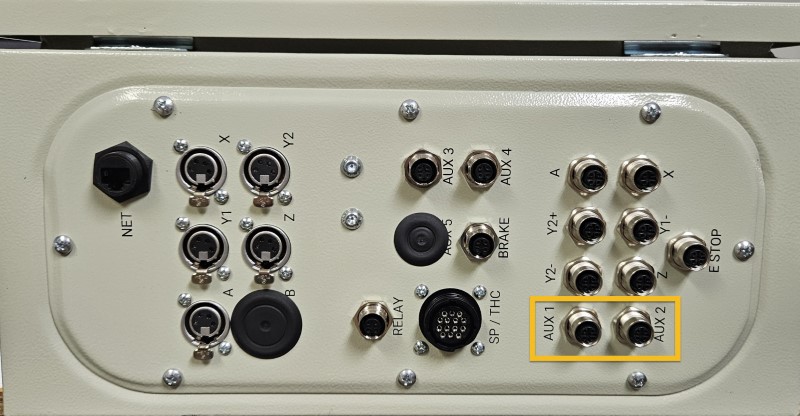
- Connect the Tool Height Setter to the Aux 2 port.
- Connect the optional Auto Z and Corner Finding Touch Plate to the Aux 1 port.
4.1.5 - Plasma Applications
4.1.5.1
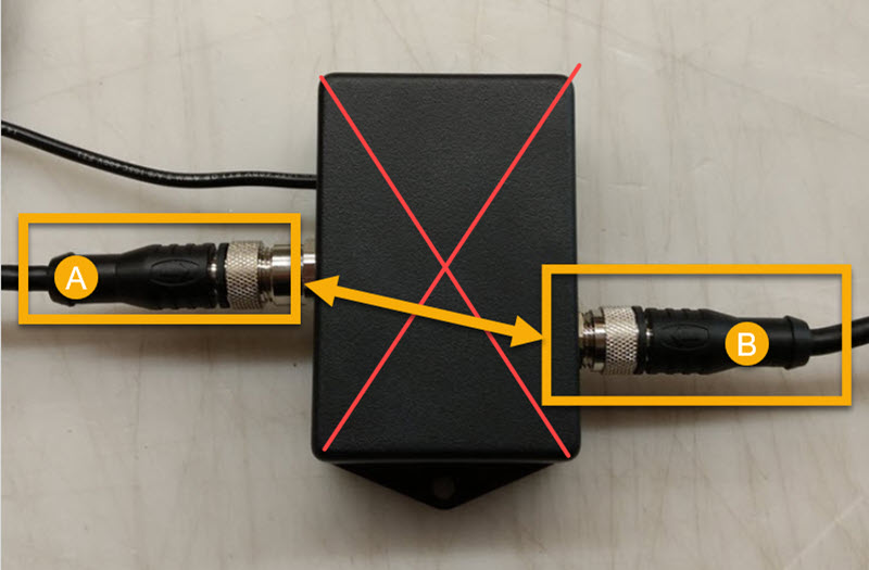
- Disconnect the existing sensor cables (A, B) from your Ohmic Protection Box.
- Connect the two sensor cables together.
Assembly Note
The Ohmic Protection Box is no longer used with EX controllers and may be removed.
4.1.5.2
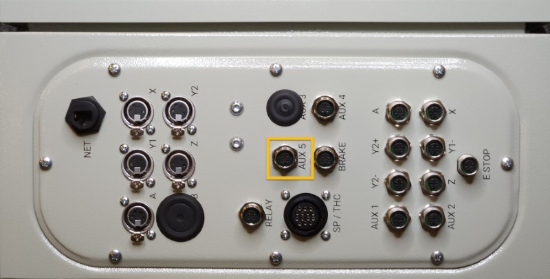
- Connect the free end of the extended Torch Mount cable directly to the Aux 5 port.
4.1.6 - Spindle / Plasma Applications

- Connect the existing SP/THC Cable to the SP/THC port.
- Depending on your current cutting method, this cable will be connected to either the Plug and Play Spindle / VFD Control Box, or your Hypertherm plasma power unit.
4.1.7
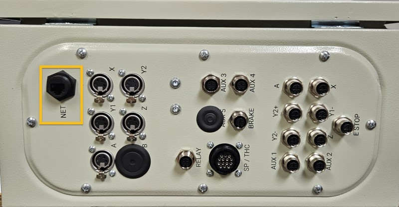
- Connect the Ethernet Cable, 10' D to the NET port.
- Connect the other end of the Ethernet cable to your control PC.
Ethernet Cable
Please ensure you're using the Ethernet cable included with the kit. The provided cable is shielded to reduce unwanted signal interference.
4.1.8
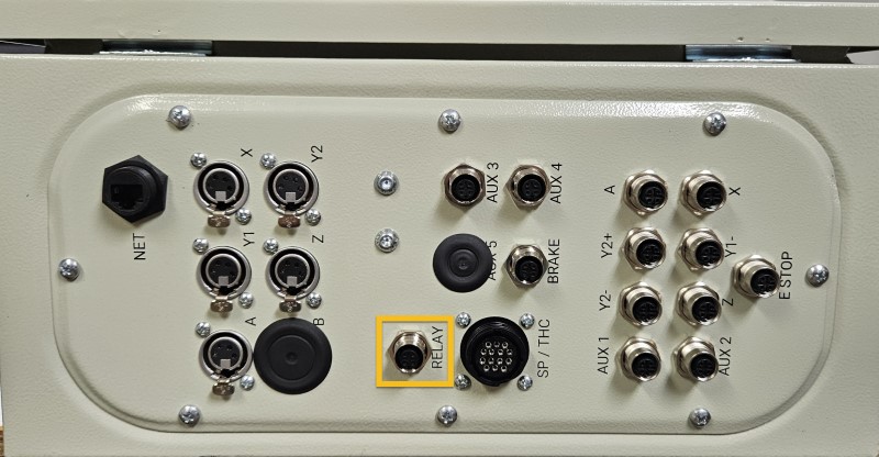
- Connect the optional Auxiliary Power Relay M12 Sensor Cable, included with the Auxiliary Power Relay, into the RELAY port.
4.1.9
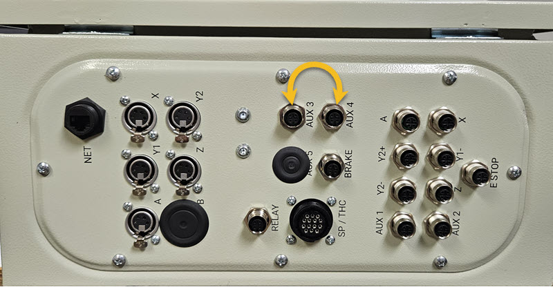
-
If you have a laser system, swap cables at the Aux 3 and Aux 4 ports.
For more information see the Laser Assembly Instructions