Benchtop PRO EX Controller and Servo Motor Retrofit
Safety Note
Ensure your CNC control box is powered off with the power cable disconnected from the box.
Assembly Note
When upgrading to the EX Control System, you must reprogram your spindle fault parameter on your VFD. Please see the VFD Reprogramming Instructions for steps on reprogramming your VFD.
Assembly Note
Following completion of this guide, you will need to re-square the gantry to the table by following our Gantry Auto-Squaring Calibration procedure.
Assembly Note - Rotary Users
See Rotary Assembly to install your Servo Motor.
1. Retrofit Z-axis
Note
You will have received one of two different kit variations. Revision notes and labels will assist in directing you to the correct instructions.
Parts List
| ID | QTY | Part/Description | Package Label |
|---|---|---|---|
1 | Z-Axis Upgrade Kit, Servo | ||
A | 4 | Grease Fitting | Z-Axis Upgrade Hardware |
B | 1 | Electromagnetic Brake Coupling | Z-Axis Upgrade Hardware |
C | 1 | Ballscrew Brake Coupling | Z-Axis Upgrade Hardware |
D | 1 | Ballscrew Coupling Later Revision | Formed during assembly |
D | 1 | Bearing Earlier Revision | Z-Axis Upgrade Hardware |
E | 1 | Ballscrew Brake Connector Harness | Z-Axis Upgrade Hardware |
F | 1 | Z-Axis End Plate with Brake | Z-Axis Upgrade Hardware |
G | 2 | M3 x 5mm Flat Head Screw | Z-Axis Upgrade Hardware |
H | 2 | M8 Roll-in T-nut | Z-Axis Upgrade Hardware |
I | 1 | Motor Support Bar | Z-Axis Upgrade Hardware |
J | 2 | M8 x 20mm Flat Head Screw | Z-Axis Upgrade Hardware |
K | 1 | Rapplon Dust Cover | Z-Axis Upgrade Hardware |
L | 1 | Motor Mount Plate | Z-Axis Upgrade Hardware |
M | 4 | M6 x 20mm Socket Head Cap Screw | Z-Axis Upgrade Hardware |
N | 1 | Cordstock | Z-Axis Upgrade Hardware |
O | 2 | M5 x 14mm Socket Head Cap Screw | Z-Axis Upgrade Hardware |
P | 1 | Damper | Z-Axis Upgrade Hardware |
Q | 1 | Servo Motor Label: Z | Servo Motor Kit |
R | 4 | M5 x 14mm Socket Head Cap Screw | Z-Axis Upgrade Hardware |
S | 4 | Flat Washer | Z-Axis Upgrade Hardware |
Tools List
| Requirement | Tool |
|---|---|
| Required | Imperial Allen Wrenches 3/32", 1/4", 5/16" |
| Required | Metric Allen Wrenches 2mm, 2.5mm, 3mm, 4mm, 6mm |
| Required | Metric Combination Wrenches 14mm, 16mm, 17mm |
| Required | 5mm socket, driver, extension |
| Required | Small Phillips Screwdriver (PH1) |
| Recommended | Medium strength thread locker |
1.1 - Remove Z-Axis
1.1.1
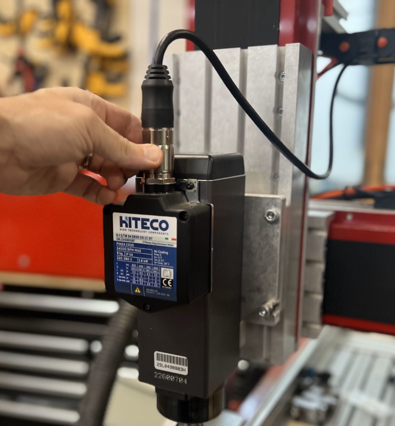
- Disconnect the M23 cable from the spindle.
1.1.2
- Remove the spindle and tramming plate together by removing the four bolts holding the tramming plate to the spindle mount adapter plate.
1.1.3
- Mark the location of your spindle mount adapter plate on the Z-axis moving plate to make reinstallation easier.
1.1.4
- Loosen the four M8 screws connecting the spindle mount adapter plate to the moving plate enough that it will slide, but still retain the T-nuts in the moving plate slots.
- Slide the plate off the bottom of the moving plate.
1.1.5
- Remove the 10 screws securing the moving plate to the Z-axis and remove the moving plate.
1.1.6
- Disconnect the sensor cable from the Z-axis proximity sensor.
1.1.7
- Disconnect the Z-axis motor cable.
1.1.8
- Remove the screws securing the dust covers.
- Remove the dust covers.
1.1.9
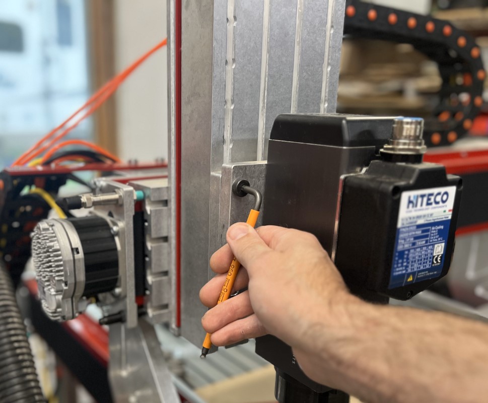
- Remove the eight M8 screws securing the Z-axis to the gantry plate.
- Remove the Z-axis from the gantry plate.
1.2 - Disassemble Z-axis
1.2.1
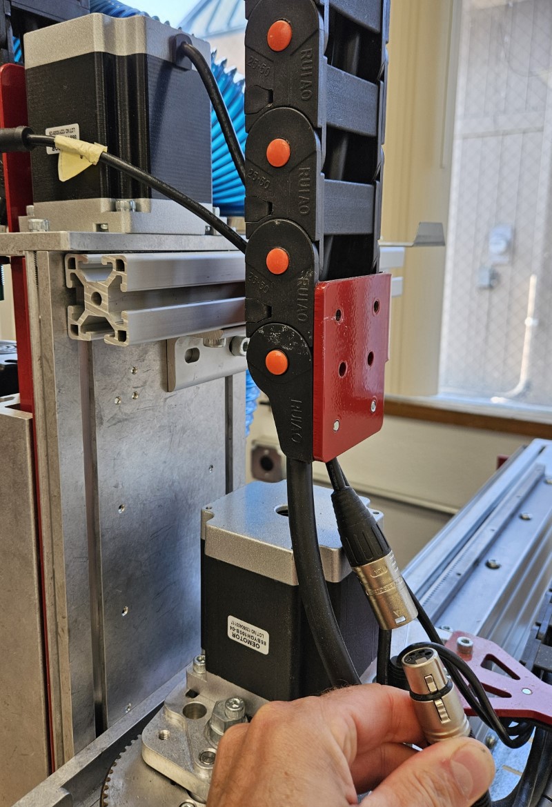
- Remove the two screws holding the Rapplon dust cover at each end of the Z-axis.
- Remove the Rapplon dust cover from the Z-axis. This may be discarded. Keep the screws and clamping bars for reinstallation later.
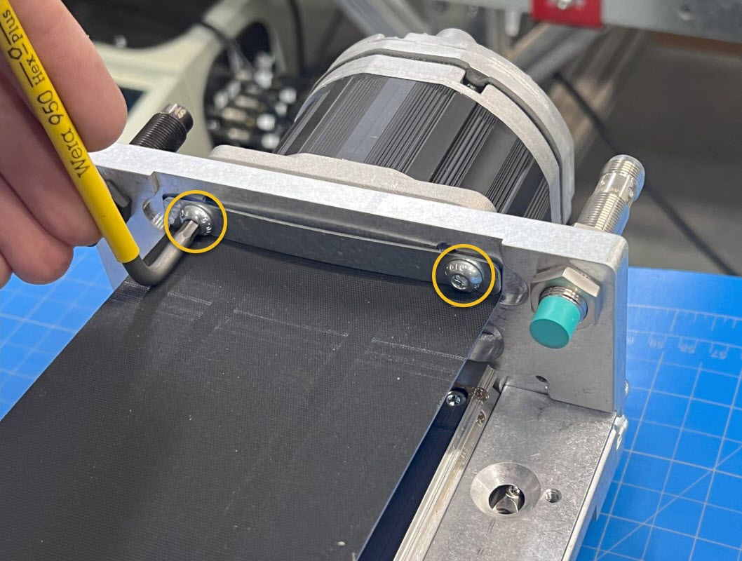
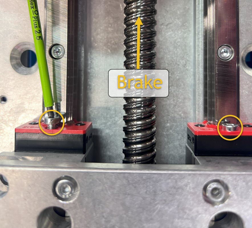
1.2.2
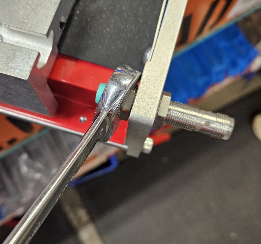
- Loosen the two set screws where the ballscrew meets the drag brake.
- You may need to manually rotate the ballscrew to access both set screws.
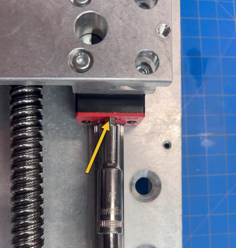
1.2.3
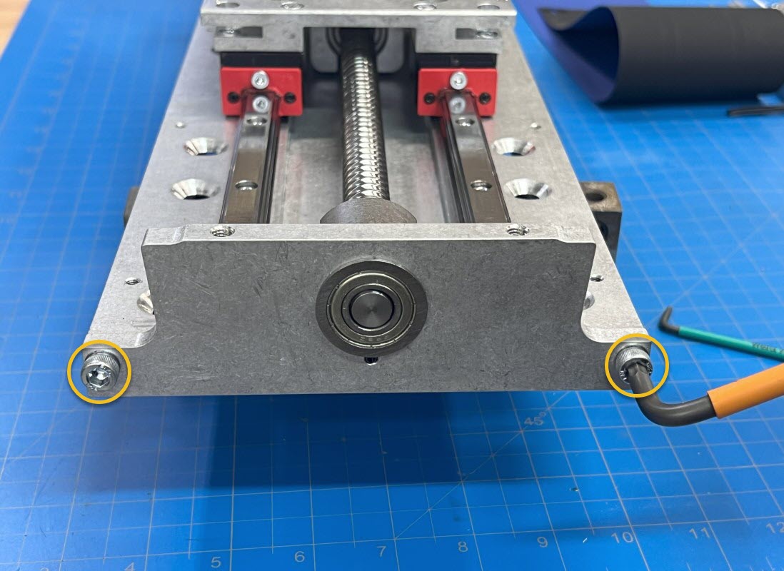
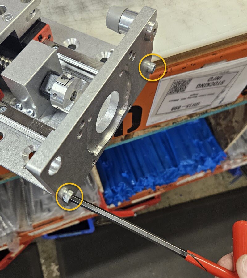
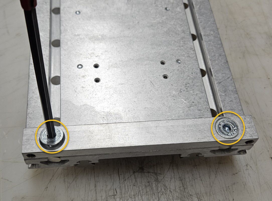
- Remove the two socket head cap screws securing the bottom plate to the Z-axis. Keep these fasteners.
- Remove the Z-axis bottom plate and drag brake from the Z-axis.
1.2.4
- At the other end of the Z-axis, remove the four socket head cap screws securing the Z-axis motor to the Z-axis.
- These fasteners will be replaced with new hardware included in the upgrade kit.
1.2.5
- Loosen the jam nuts securing the Z-axis proximity sensor with a 17mm wrench.
- Remove and keep the proximity sensor and jam nuts.
1.2.6
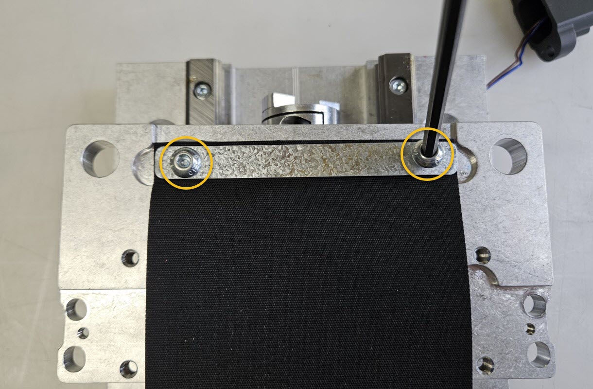
- Remove the two socket head cap screws securing the motor mount plate to the Z-axis.
- Remove the motor mount plate.
1.2.7
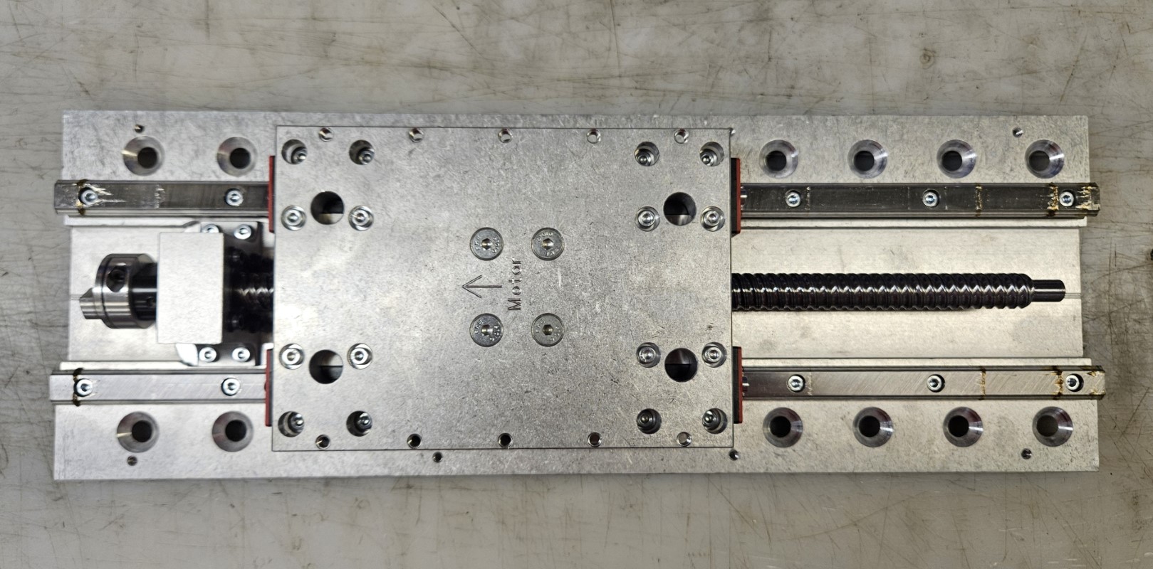
- Your Z-axis disassembly is complete and should look like this, above.
1.3 - Install New Grease Fittings
The new included end plates on your Z-axis are designed to allow you to grease your Z-axis bearing blocks. To facilitate greasing, grease fittings need to be added to your bearing blocks. Once these are added you can grease your axis by removing the bottom of the rapplon and the motor and then back driving the moving plate to each end of the axis. The holes in the end plates will allow you to reach the grease fittings with a needle tip grease gun.
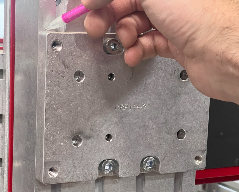
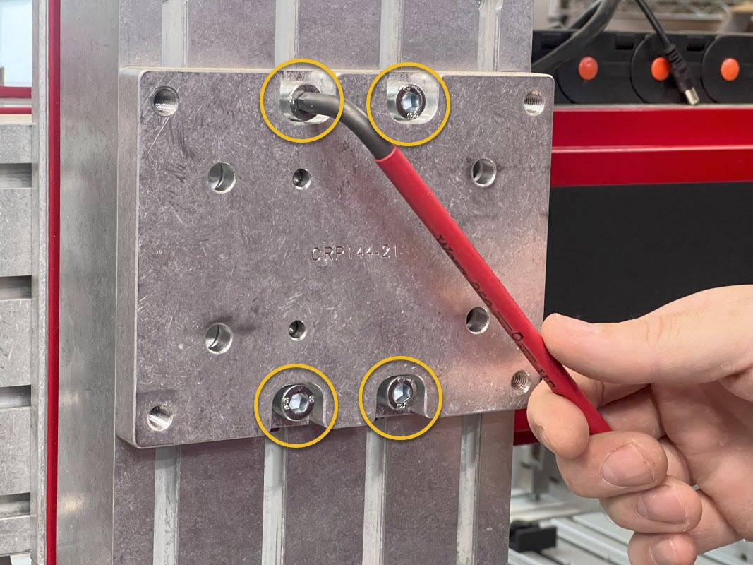
1.3.1
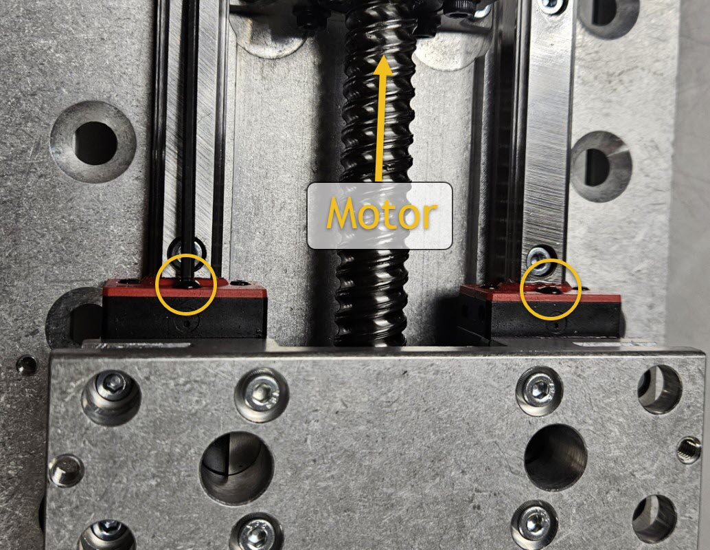
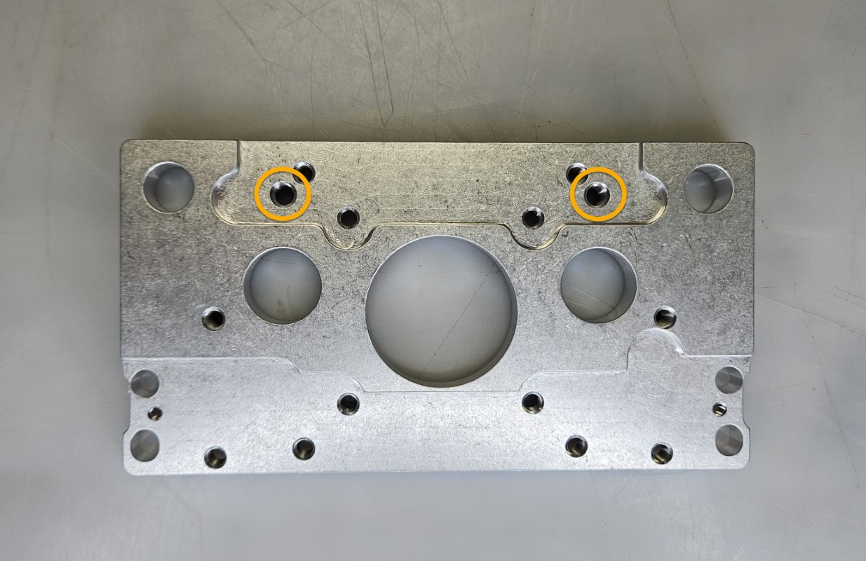
- Remove one center screw from the exposed end of each existing Z-axis bearing block, as shown.
- The motor end will have button head screws.
- The brake end will have socket head cap screws.
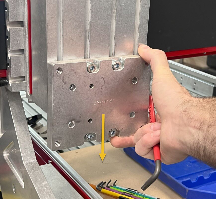
1.3.2
- Install the provided Grease Fittings A with a 5mm socket.
1.4 - Install New Brake and End Plate
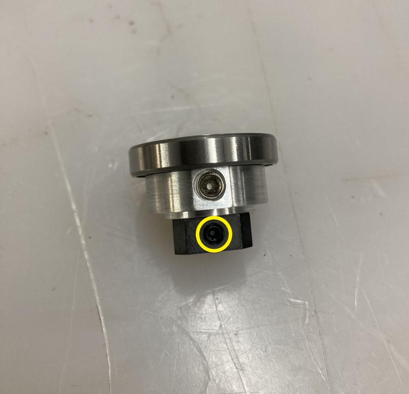
Revision Note
You will have received one of two different kit variations. Use the pictures below to identify your variation and follow the correct instructions.
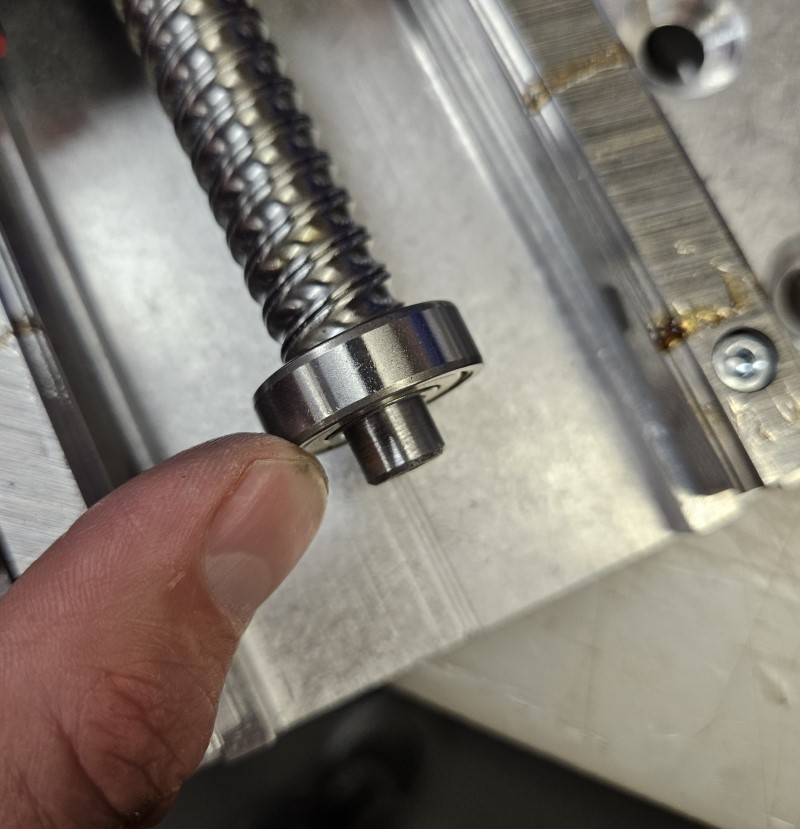
- If the bearing is pressed onto the coupling, follow the steps labeled Later Revision:

Later Revision - If the bearing and coupling are separate, follow the steps labeled Earlier Revision:

Earlier Revision
1.4.1
Later Revision
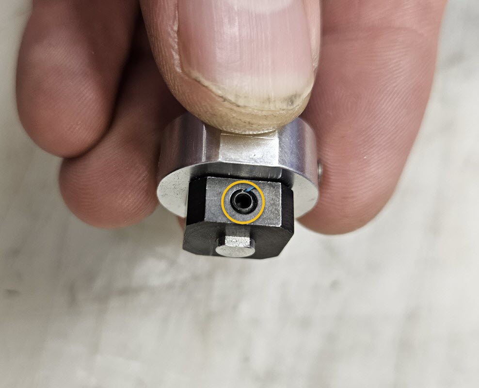
- Attach the Electromagnetic Brake Coupling B to the Ballscrew Brake Coupling C, sliding it onto the shaft as far as it will go.
- Tighten the set screw on the Electromagnetic Brake Coupling to secure it to the Ballscrew Brake Coupling. This assembly is now the Ballscrew Coupling D.
1.4.1
Earlier Revision
- Attach the Electromagnetic Brake Coupling B to the Ballscrew Brake Coupling C, sliding it onto the shaft as far as it will go.
- Tighten the set screw on the Electromagnetic Brake Coupling to secure it to the Ballscrew Coupling.
1.4.2
Later Revision
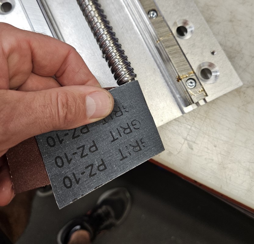
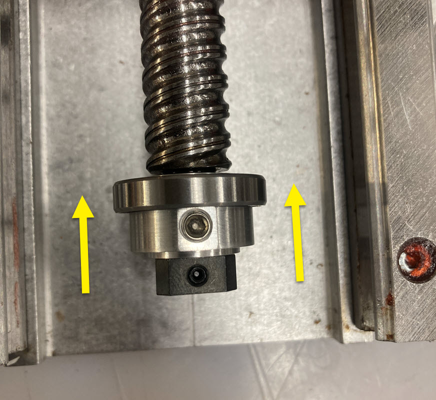
- Slide the Ballscrew Coupling D onto the ballscrew shaft until it stops. There will be a gap between the bearing and the ballscrew shoulder.
- You may need to remove the burrs created by the previous drag brake set screws. Emory cloth or fine sand paper may be used to smooth these surface imperfections.
1.4.2
Earlier Revision
- Slide the Bearing D onto the ballscrew shaft.
- You may need to remove the burrs created by the previous drag brake set screws. Emory cloth or fine sand paper may be used to smooth these surface imperfections.
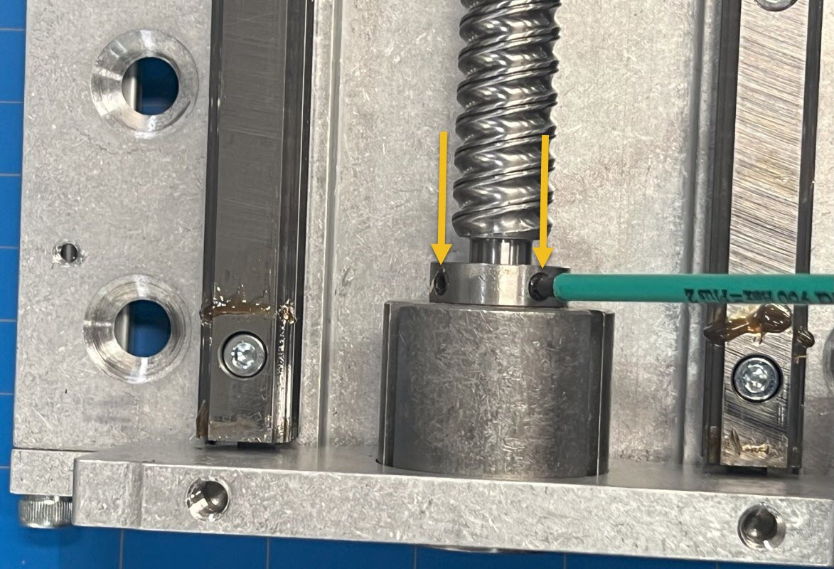
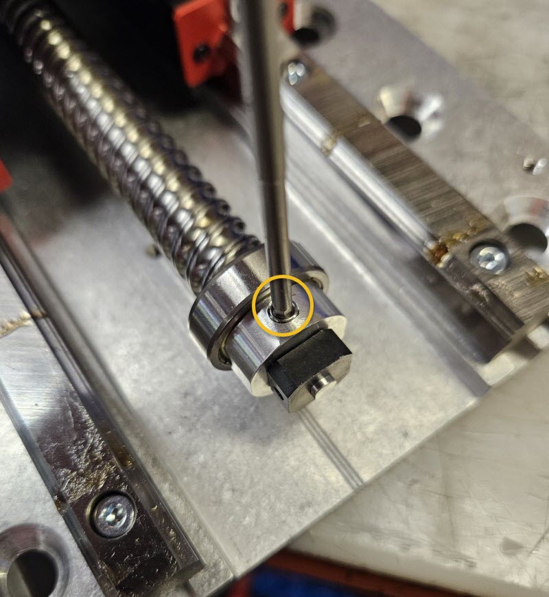
1.4.3
Later Revision
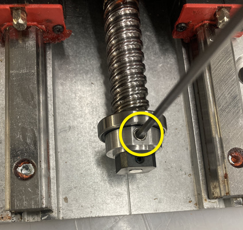
- Tighten both set screws to secure the Ballscrew Coupling D.
Assembly Note
We recommend applying medium strength thread locker to these set screws during installation of the Ballscrew Coupling assembly.
1.4.3
Earlier Revision
- Attach the Ballscrew Coupling assembly to the ballscrew. Tighten both set screws to secure it.
Assembly Note
We recommend applying medium strength thread locker to these set screws during installation of the Ballscrew Coupling assembly.
1.4.4
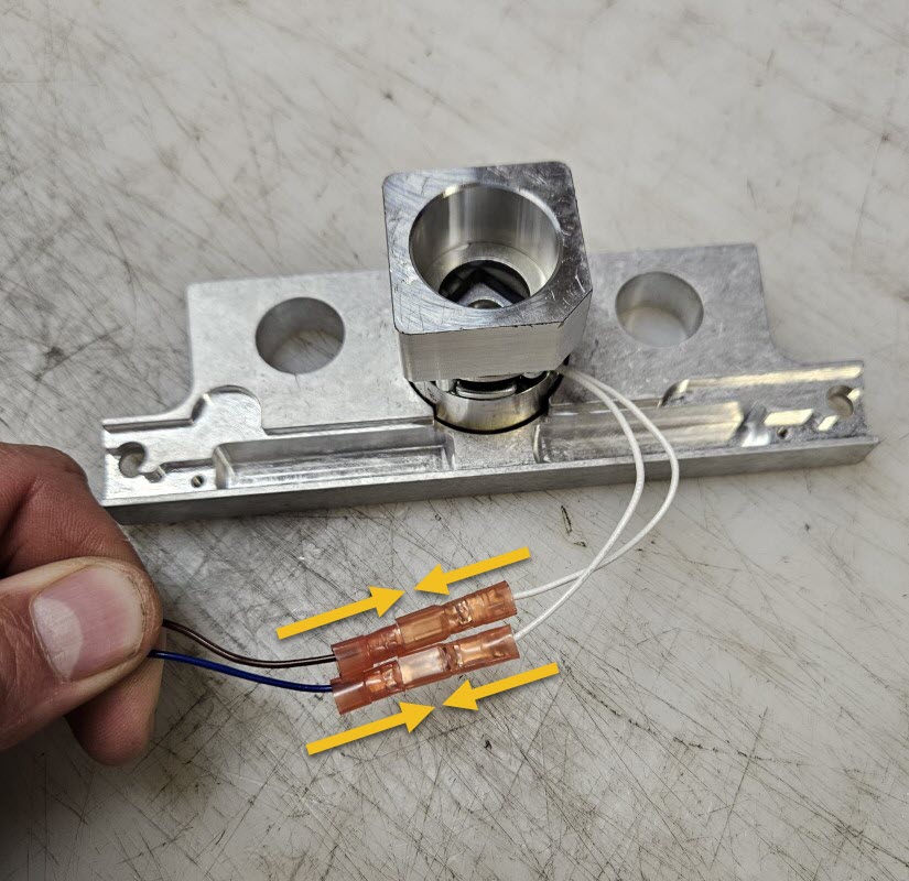
- Connect the Ballscrew Brake Connector Harness E wires to the Z-Axis End Plate with Brake F wires.
- The polarity is not important and the wires may be connected in either orientation.
1.4.5
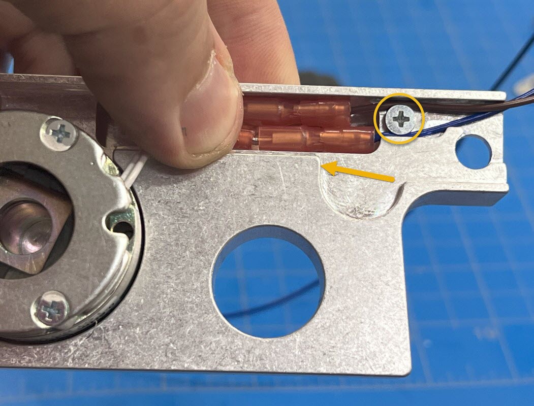
- Press the wire disconnects into the pocket on the Z-Axis End Plate with Brake.
- Using one M3 x 5mm Flat Head Screw G , lightly secure the wires being careful not to damage them. Apply only enough pressure with the screw head that the wires are not able to move freely anymore.
- When complete, the wires should exit the End Plate on the right side.
1.4.6
- Position Z-Axis End Plate with Brake assembly onto the bottom of the Z-axis.
- Ensure wires are retained in the machined pocket at the bottom of the End Plate and not pinched.
- Slide the End Plate assembly onto the bearing. Slowly rotate the ballscrew until the Brake Coupling aligns with the brake and allows the End Plate to sit flush with the Z-axis with no extra force.
1.4.7
- Loosely attach the End Plate with two original socket head cap screws.
1.4.8
- Ensure the reference surface is tight to the Z-Axis End Plate and that the plate is pressed down against the Z-axis.
- Tighten the two End Plate socket head cap screws.
1.4.9
- Attach the included Rapplon Dust Cover K to the Z-Axis End Plate, reusing the original screws and clamping bar. The other end will be attached in a later step.
1.5 - Install New Motor Mount Plate
1.5.1
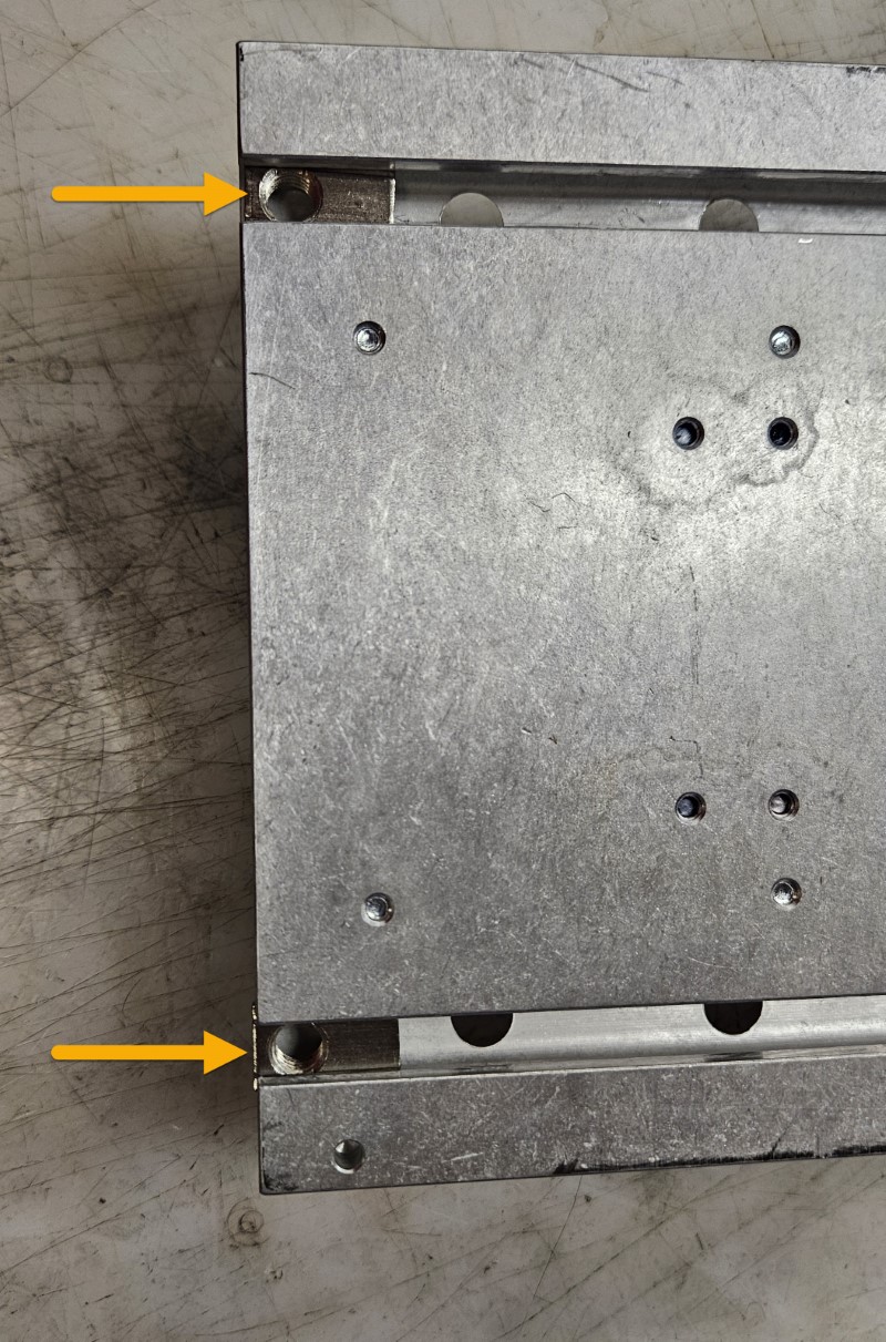
- Turn the Z-axis over and slide two M8 Roll-in T-nuts H into the rear slots from the open end, as shown.
- Note that the long side of the T-nut goes in first.
1.5.2
- Loosely attach the Motor Support Bar I to the back of the Z-axis using M8 x 20mm Flat Head Screws J. These will be fully tightened in a later step.
1.5.3
- Attach the Rapplon Dust Cover K to the new Motor Mount Plate L , using the indicated holes, with the remaining screws and clamping bar removed during disassembly.
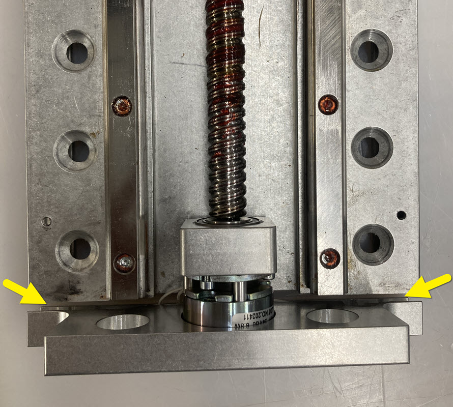
1.5.4
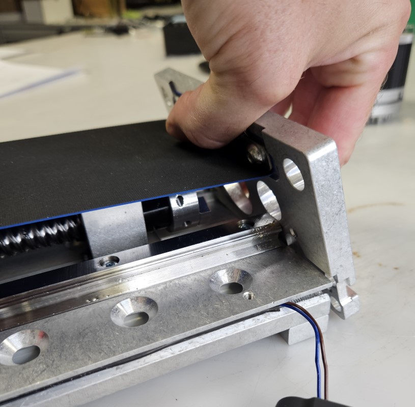
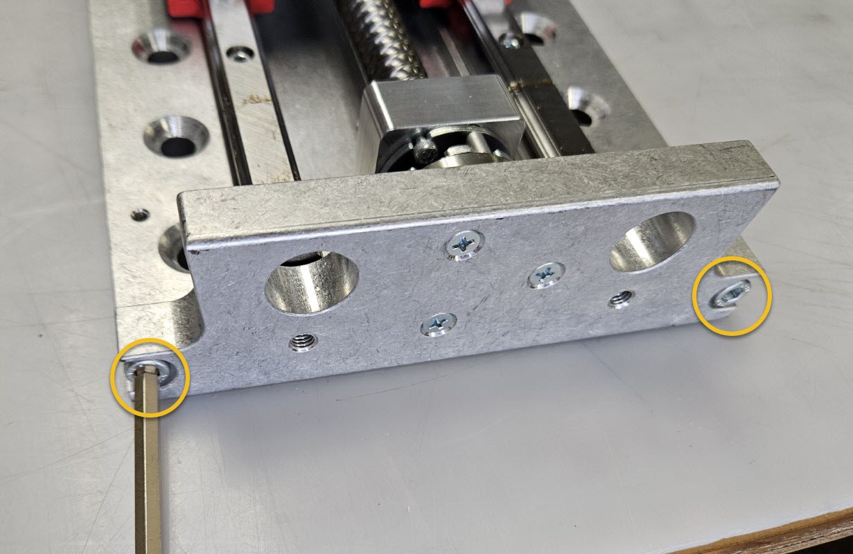
- Attach the Motor Mount Plate L to the Z-axis, using the plate as a lever to stretch the Rapplon Dust Cover K tight.
- Loosely install two M6 x 20mm Socket Head Cap Screws M through the Motor Mount Plate L and into the Z-axis extrusion.
- Ensure the reference surface of the end plate is tight against the Z-axis extrusion (see Fig. 2, above) and fully tighten the M6 screws.
1.5.5
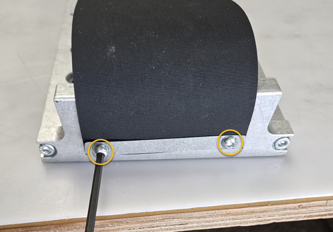
- Install two M6 x 20mm Socket Head Cap Screws M through the Motor Mount Plate L and into the Motor Support Bar I. Fully tighten these M6 fasteners.
- On the back of the Z-axis, fully tighten the two previously installed M8 x 20mm Flat Head Screws J securing the Motor Support Bar I to the Z-axis.
1.6 - Complete Retrofit Modifications
1.6.1
- Secure the Ballscrew Brake Connector Harness wires to the Z-axis by pressing wires and Cordstock N into the groove on the side of the Z-axis extrusion.
1.6.2
- Using one M3 x 5mm Flat Head Screw G , lightly secure the wires being careful not to damage them. Apply only enough pressure with the screw head that the wires are not able to move freely anymore.
1.6.3
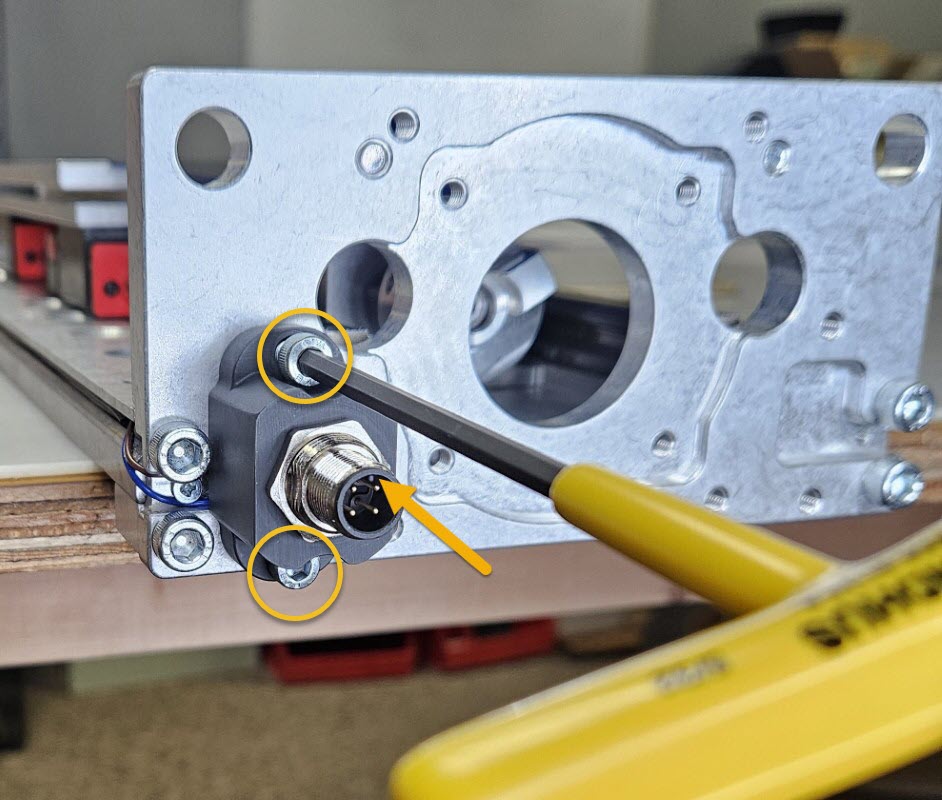
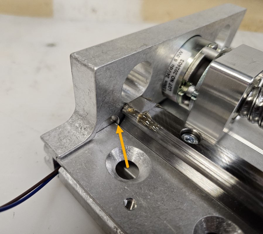
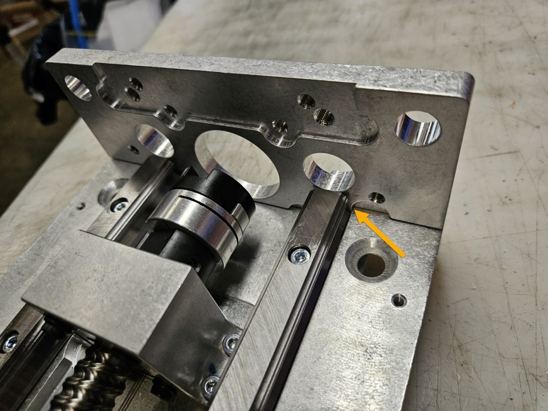
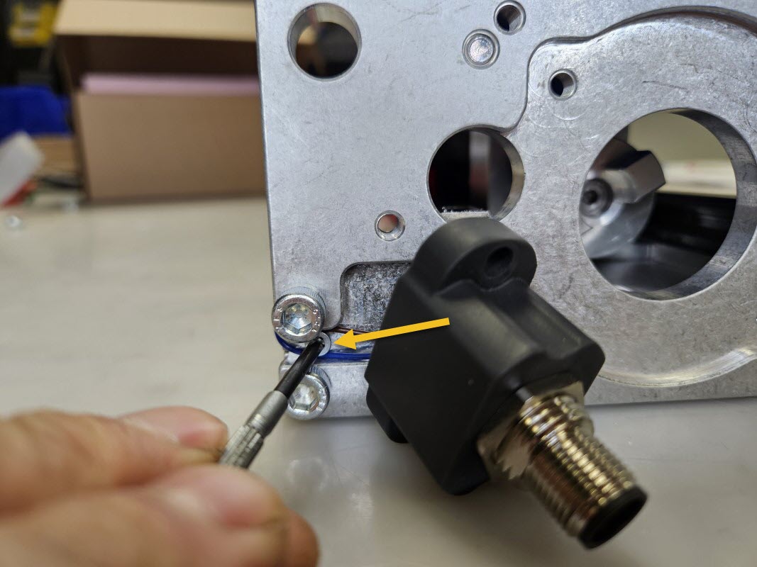
- Attach the Ballscrew Brake Connector Harness E to the motor plate with M5 x 14mm Socket Head Cap Screws O, being careful not to overtighten and crack the connector standoff.
- Ensure the M12 connector alignment guide (indicated by arrow) is oriented toward the front of the Z-axis.
1.6.4
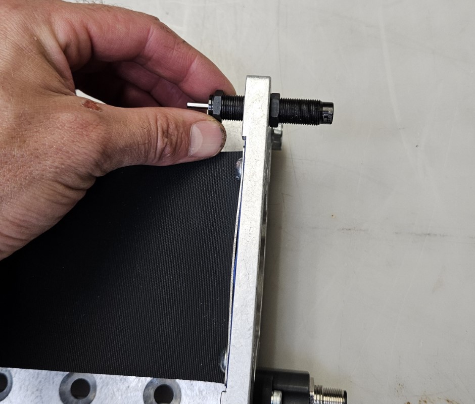
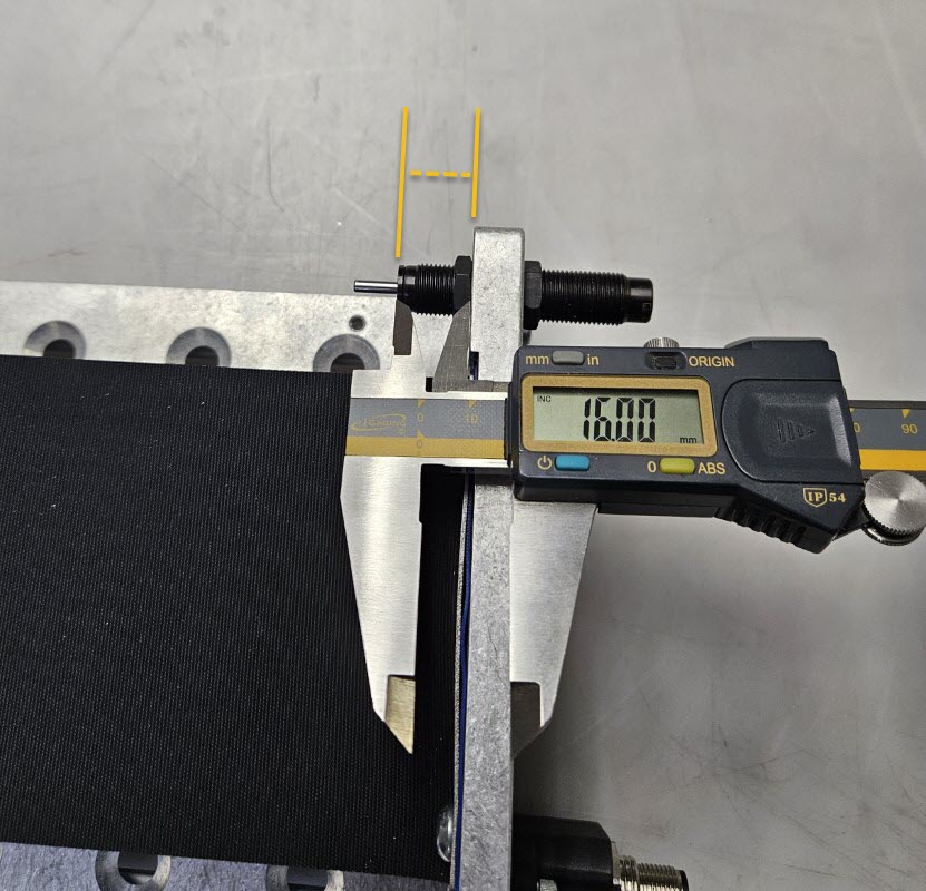
- Install the Damper P on the Motor Mount Plate L opposite the Ballscrew Brake Connector Harness, as shown.
- Using the included jam nuts, adjust the Damper so that the face of its housing is 16mm (5/8") from the inside face of the motor mount plate.
- Tighten the jam nuts to lock the Damper in position.
1.6.5
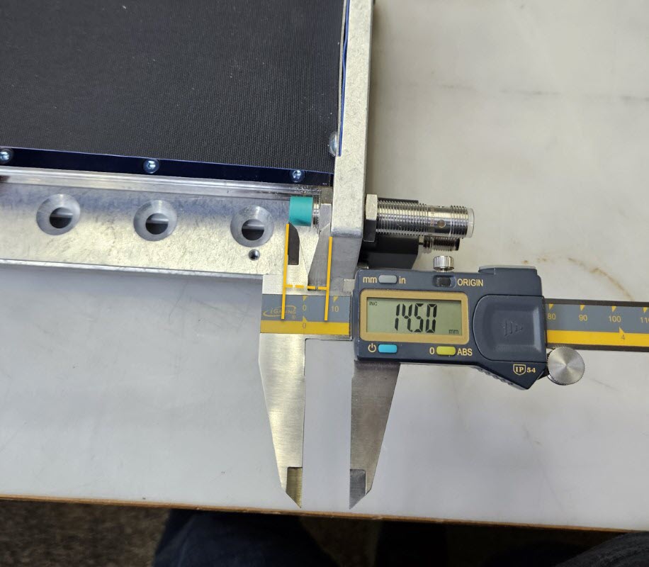
- Reinstall the proximity sensor removed during disassembly.
- Using the original jam nuts, adjust the sensor so that the face is 14.5mm (9/16") from the inside face of the motor mount plate.
- Tighten the jam nuts to lock the sensor in position.
Assembly Note
It is important that the Z-axis moving plate stops against the damper before impacting the proximity sensor or the sensor may be damaged.
1.6.6
Assembly Note
Your kit includes four servo motors that are specifically tuned for each axis and are labeled accordingly. Ensure the motors are installed on the proper axis for proper performance of your CNC machine.
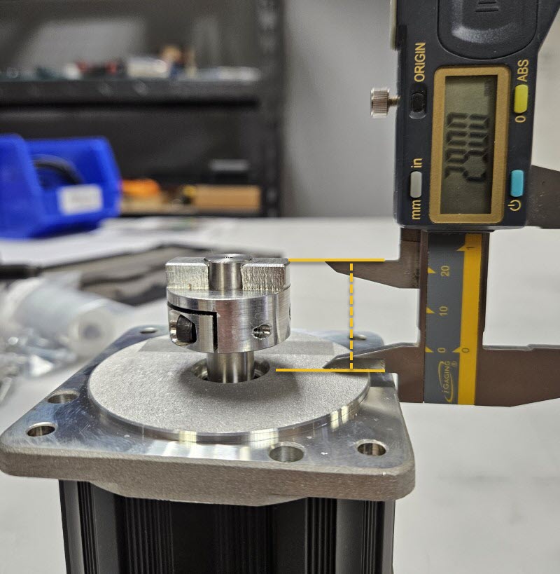
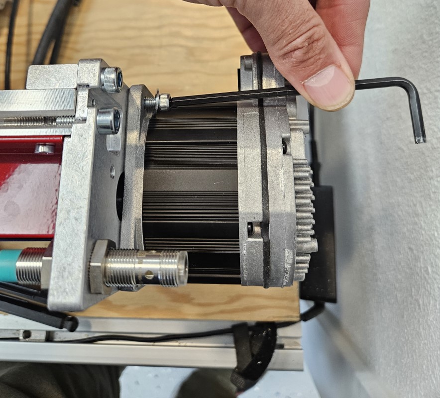
- To prepare the Servo Motor Q for installation, remove the tape holding the motor key in place on the motor shaft.
- Remove the oldham coupler from your stepper motor and reinstall it on the Servo Motor.
- The top of the coupler should be 29mm (1-1/8") above the motor boss, as shown.
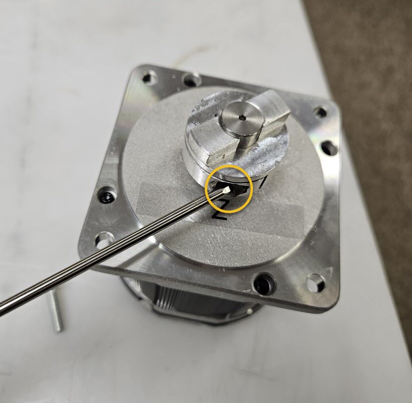
- Tighten the clamping screw to lock the oldham coupler in place.
1.6.7
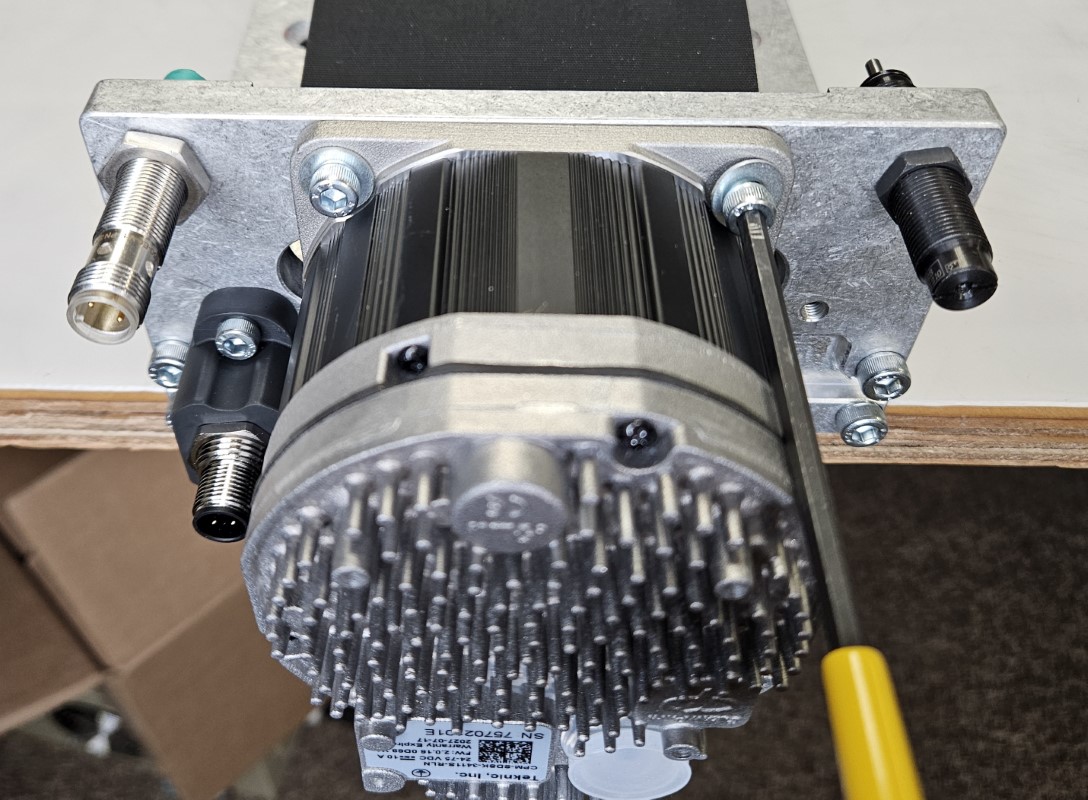
- Attach the Servo Motor Q to the Motor Mount Plate L using four M5 x 14mm Socket Head Cap Screws R and four Flat Washers S.
- The motor cable connectors should be facing the back of the Z-axis (opposite the Rapplon Dust Cover).
Reassembly Note
Your Z-axis is now ready to be reinstalled on your machine. Follow the removal instructions provided here in reverse order.
2. Retrofit Table and Gantry Axes
Parts List
| ID | QTY | Part/Description | Package Label |
|---|---|---|---|
1 | BT PRO Servo Bumper & Damper Upgrade Hardware | ||
A | 6 | M8 Roll-in T-nut | BT PRO Servo Bumper & Damper Upgrade Hardware |
B | 3 | Motor Support Bar | BT PRO Servo Bumper & Damper Upgrade Hardware |
C | 6 | M8 x 20mm Flat Head Screw | BT PRO Servo Bumper & Damper Upgrade Hardware |
D | 3 | Motor Mount Plate | BT PRO Servo Bumper & Damper Upgrade Hardware |
E | 12 | M6 x 20mm Socket Head Cap Screw | BT PRO Servo Bumper & Damper Upgrade Hardware |
F | 3 | Damper | BT PRO Servo Bumper & Damper Upgrade Hardware |
G | 12 | M5 x 14mm Socket Head Cap Screw | BT PRO Servo Bumper & Damper Upgrade Hardware |
H | 12 | Flat Washer | BT PRO Servo Bumper & Damper Upgrade Hardware |
I | 3 | Servo Motor Labels: X, Y (2x) | Servo Motor Kit |
Tools List
| Requirement | Tool |
|---|---|
| Required | 4mm Allen Wrench |
| Required | 5mm Allen Wrench |
| Required | 6mm Allen Wrench |
| Required | Flathead Screwdriver |
2.1 - Motor End Disassembly
2.1.1
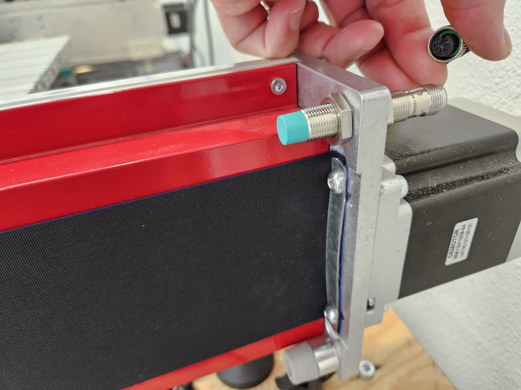
- Disconnect the sensor cable from the proximity sensor.
- Disconnect the motor cable from the stepper motor.
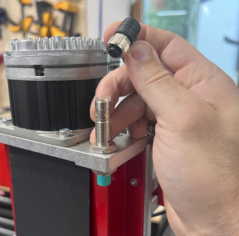
2.1.2
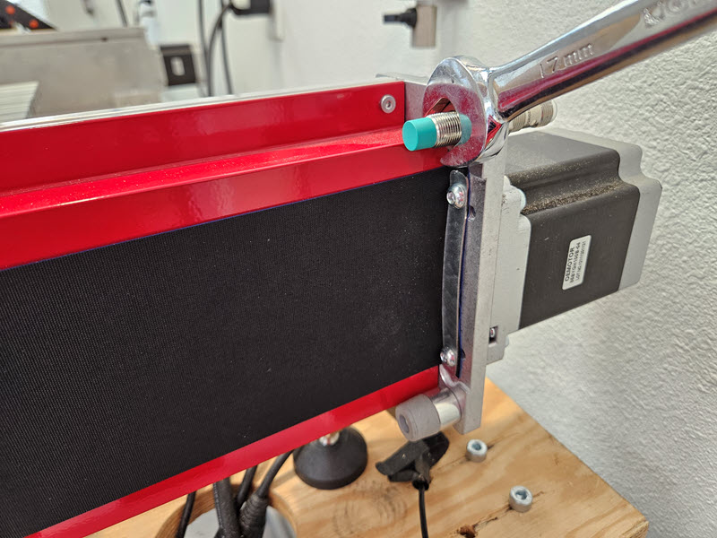
- Remove the proximity sensor by loosening and removing the jam nut with a 17mm combination wrench. Keep the proximity sensor for reuse.
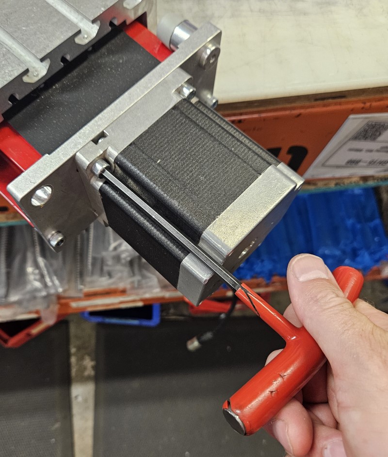
2.1.3
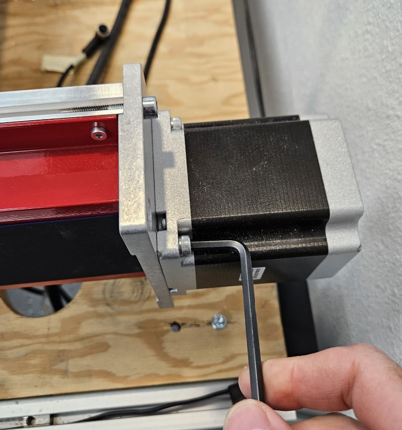
- Remove the stepper motor.
2.1.4
- Remove the two screws holding the Rapplon dust cover to the motor mount plate.
- Keep the screws and clamping bars for reinstallation later.
- Note that the red dust covers do not need to be removed for the table or gantry axis retrofit.
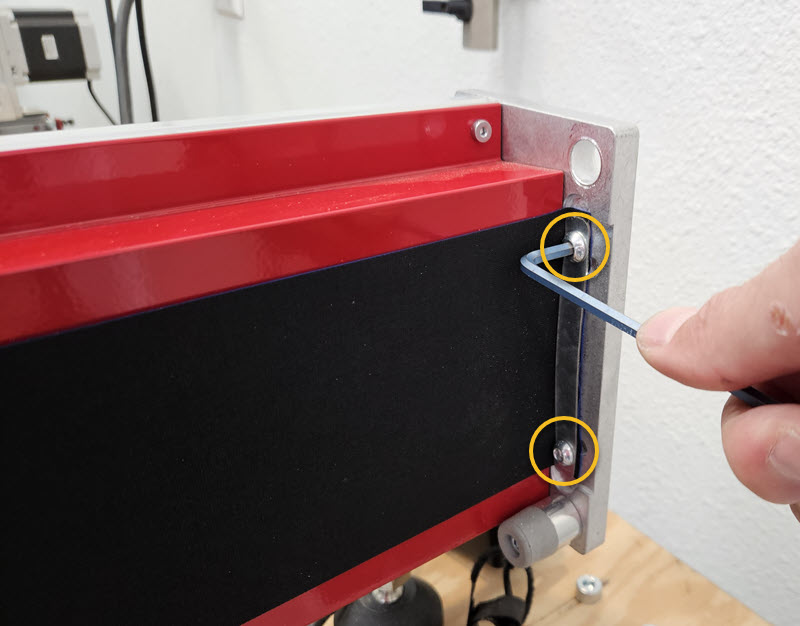
2.1.5
- Remove the two socket head cap screws securing the motor mount plate to the axis.
2.2 - Install Motor Plate
2.2.1
- For table axes, if your foot plate is adjacent to the motor mount plate, loosen the foot plate and slide it along the axis to make room for installing the motor support bar.
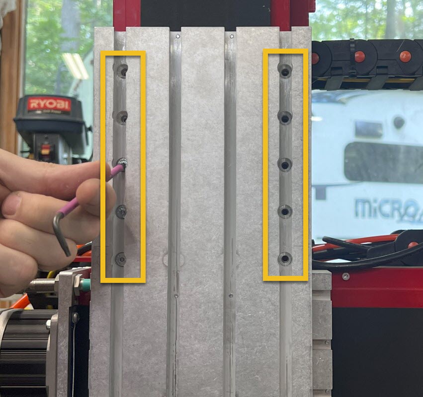
2.2.2
- Slide two M8 Roll-in T-nuts A into the slots on the back of the axis, as shown. Note that the long side of the t-nut goes in first.
2.2.3
- Attach the Motor Support Bar B to the back of the axis using M8 x 20mm Flat Head Screws C. Leave screws slightly loose in this step.
2.2.4
- Attach the Rapplon dust cover to the new Motor Mount Plate D, using the indicated holes, with the screws and clamping bar removed during disassembly.
2.2.5
- Attach the Motor Mount Plate to the axis, using the plate as a lever to stretch the Rapplon dust cover tight.
- Install M6 x 20mm Socket Head Cap Screws E through the Motor Mount Plate and into the axis extrusion.
- Fully tighten the socket head cap screws.
Assembly Note
If M6 x 20mm screws conflict with dust cover screws, remove the dust cover screws. Dust cover performance will not be affected.
2.2.6
- Install two M6 x 20mm Socket Head Cap Screws E through the Motor Mount Plate and into the Motor Support Bar and tighten.
- Fully tighten the two M8 x 20mm Flat Head Screws securing the Motor Support Bar to the axis.
2.2.7
- If necessary, slide the footplate back against the motor support bar and tighten the screws.
2.3 - Install Remaining Components
2.3.1
- Install the Damper F on the Motor Mount Plate, as shown.
- Using the included jam nuts, adjust the Damper so that the face of its housing is distanced from the inside face of the Motor Mount Plate according to the table below.
- Tighten the jam nuts.
| Gantry Axis | Table Axis |
|---|---|
| 14mm (9/16") | 16mm (5/8") |
2.3.2
Assembly Note
The Y-axis sensor locations have changed and are opposite of the machine coordinate system. This is necessary for the machine to home properly and does not affect the actual machine coordinate system. Ensure that your sensors are plugged into the controller ports labeled in the drawing.

- Install a proximity sensor at the indicated locations. Adjustments will be made later.
- Your Y1- sensor will be relocated to the motor end (back) of the machine and will complete changes to Y1.
- Swap the sensor cables for Y2- and Y2+ at the control box end to complete changes to Y2.
2.3.3
- Adjust the jam nuts so that the face of the sensor is distanced from the inside face of the motor mount plate according to the table below.
- Tighten the jam nuts.
- Note it is important that the axis moving plate stops against the damper before impacting the proximity sensor or the sensor may be damaged.
| Sensor | Distance |
|---|---|
| X- Sensor | 12.5mm (1/2") |
| X+ Sensor | 22mm (7/8") |
| Y1- Sensor | 14.5mm (9/16") |
| Y2- Sensor | 14.5mm (9/16") |
| Y2+ Sensor | 22mm (7/8") |
| Z+ Sensor | 14.5mm (9/16") |
2.3.4
Assembly Note
Your kit includes four servo motors that are specifically tuned for each axis and are labeled accordingly. Ensure the motors are installed on the proper axis for proper performance of your CNC machine.
- To prepare the Servo Motor I for installation, remove the tape holding the motor key in place on the motor shaft.
- Remove the oldham coupler from your stepper motor and reinstall it on the Servo Motor.
- The top of the coupler should be 29mm (1-1/8") above the motor boss, as shown.
- Tighten the clamping screw to lock the oldham coupler in place.
2.3.5
- Attach the Servo Motor I to the Motor Mount Plate using four M5 x 14mm Socket Head Cap Screws G and four Flat Washers H.
- The motor cable connectors should be facing the back of the axis (opposite the Rapplon dust cover).
- Reconnect the cable to the proximity sensor.
Repeat Section 2 for both table axes and the gantry axis.
3. Tool Height Setter
Parts List
| ID | QTY | Part/Description | Package Label |
|---|---|---|---|
1 | Tool Height Setter Kit | CRP5230-00-12 | |
A | 1 | Tool Height Setter Assembly | Tool Height Setter Kit |
B | 1 | Tool Height Setter Cover | Part of Tool Setter Assembly |
C | 2 | M3 x 8mm Socket Head Cap Screw | Part of Tool Setter Assembly |
1 | Tool Height Setter Hardware | CRP5230-00-HW | |
D | 1 | Adapter Plate | Tool Height Setter Hardware |
E | 1 | M8 x 12mm Socket Head Cap Screw | Tool Height Setter Hardware |
F | 5 | M3 x 8mm Socket Head Cap Screw | Tool Height Setter Hardware |
G | 1 | Tramming Cam | Tool Height Setter Hardware |
H | 1 | M6 x 30mm Socket Head Cap Screw | Reuse Existing |
Tools List
| Requirement | Tool |
|---|---|
| Required | 2.5mm Allen Wrench |
| Required | 3mm Allen Wrench |
| Required | 6mm Allen Wrench |
3.1 - Tool Height Setter Installation
3.1.1

- Install the Adapter Plate D on the end of the benchtop table axis.
- Remove the existing M6 x 30mm Socket Head Cap Screw H holding the top of the axis end plate in place and use that to connect the adapter plate to the axis.
- Install the M8 x 12mm Socket Head Cap Screw E to secure the adapter plate.
- Install one M3 x 8mm Socket Head Cap Screw F in the adapter plate.
3.1.2

- Insert the Tramming Cam G into the pocket on the Adapter Plate.
3.1.3

- Remove the Cover B from the Tool Height Setter Assembly A by removing the M3 x 8mm screws C.
3.1.4

- Attach the Tool Height Setter Assembly A to the Adapter Plate using M3 x 8mm Screws F.
3.2 - Tool Height Setter Tramming
Section Note
Prior to tramming the Tool Height Setter, ensure that your machine table has been squared and leveled, and your spindle has been trammed.
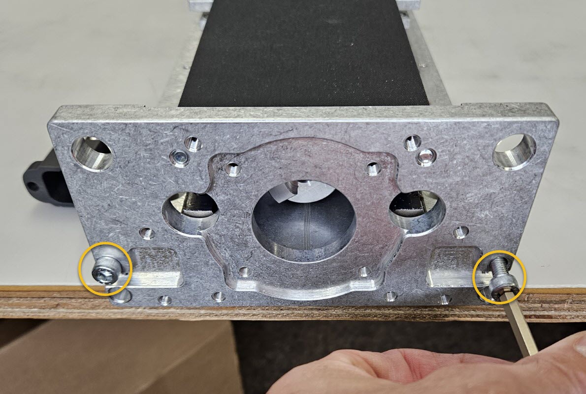
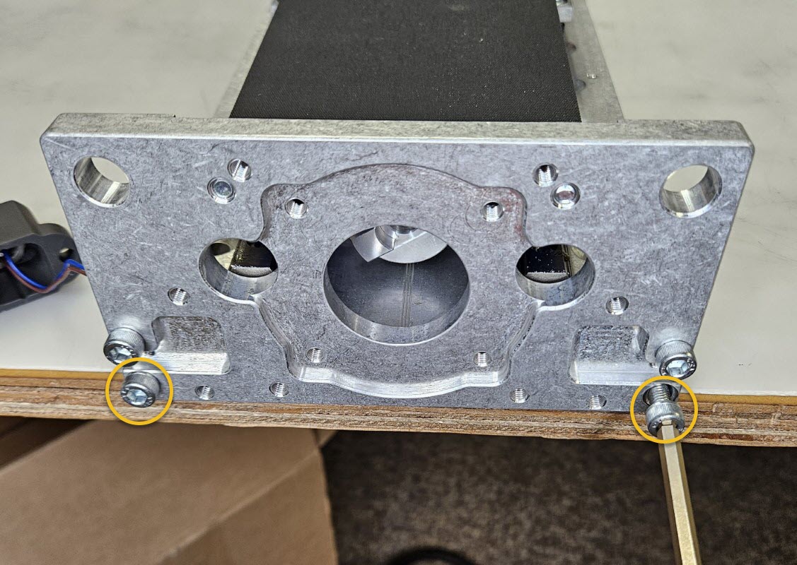
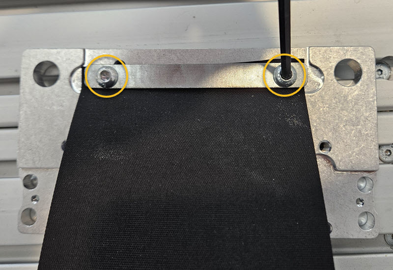
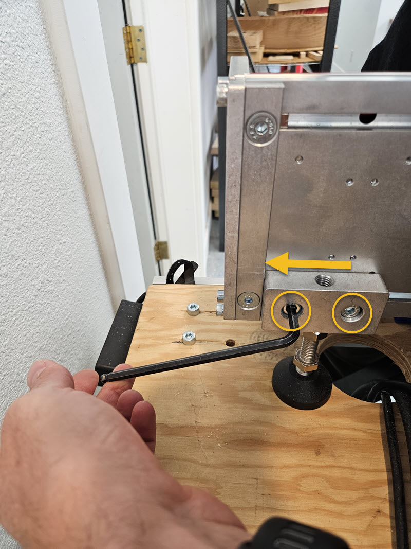
3.2.1

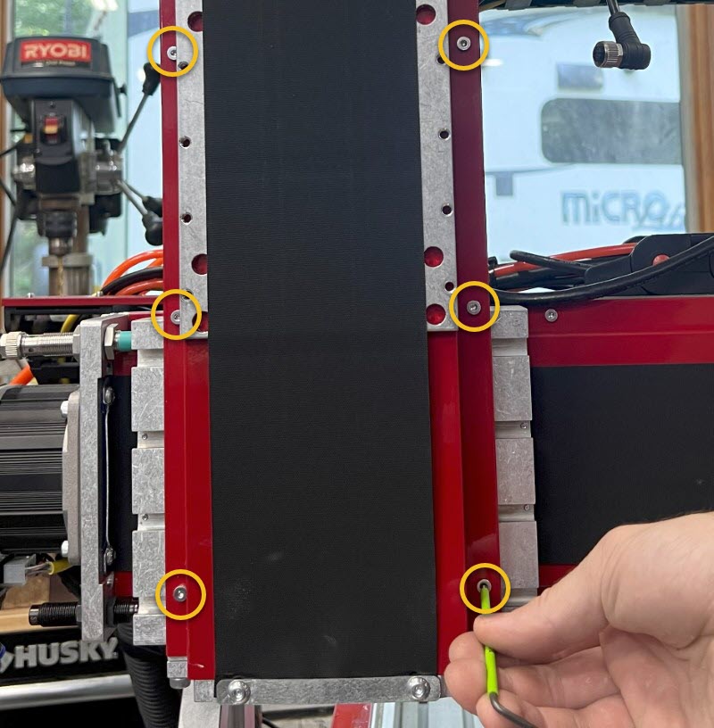
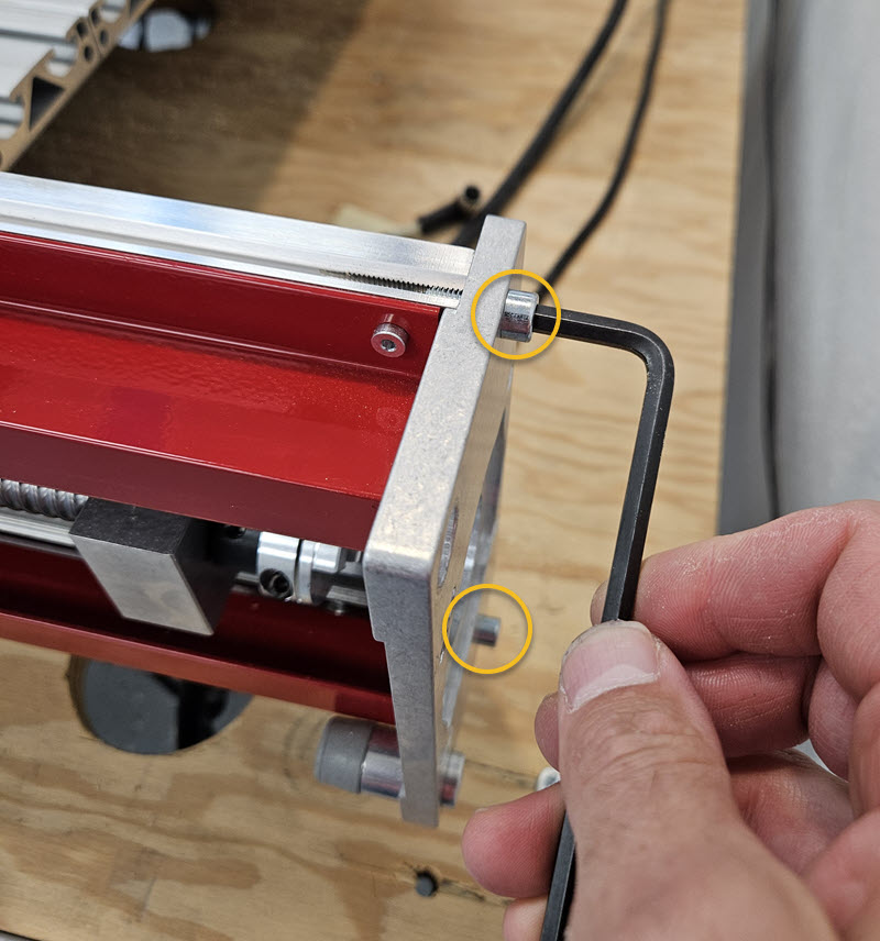
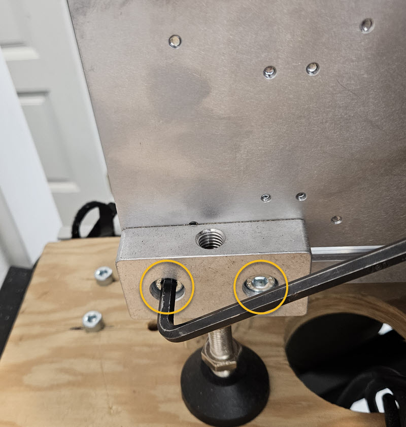
- Loosen the four indicated screws to tram the Tool Height Setter in the x-axis direction.
3.2.2

- Set a reference block on top of the Tool Setter to extend the height of the touch surface. The block needs to have two parallel surfaces approximately 2" apart.
- Slowly jog the spindle nose down to the reference block.
- Rotate the Tramming Cam until the touch surface of the Tool Height Setter is parallel to the spindle nose.
- Retighten the four screws previously loosened to lock the position.
3.2.3
Section Note
It is likely that your Tool Height Setter will not need tramming in this orientation. Only tram this direction if it is not parallel to your work surface.

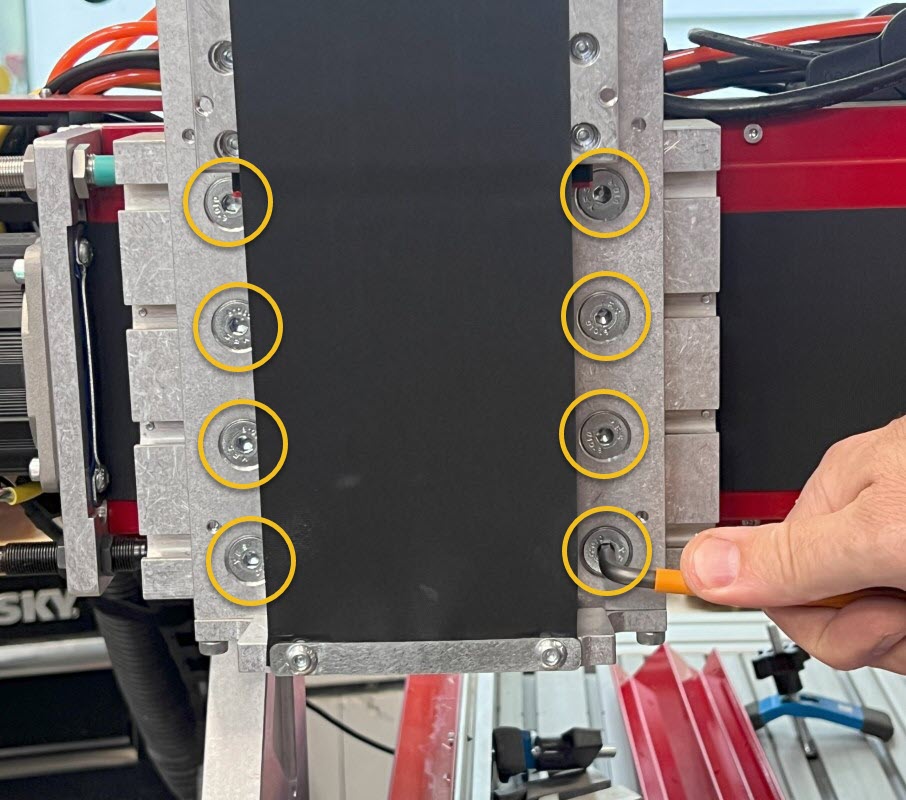
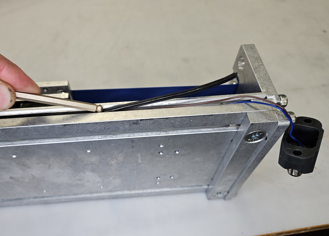
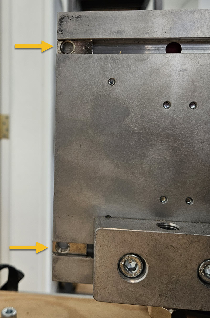
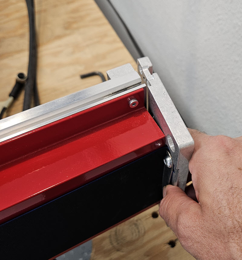
- Loosen the screws noted to tram the Tool Height Setter in the y-axis direction.
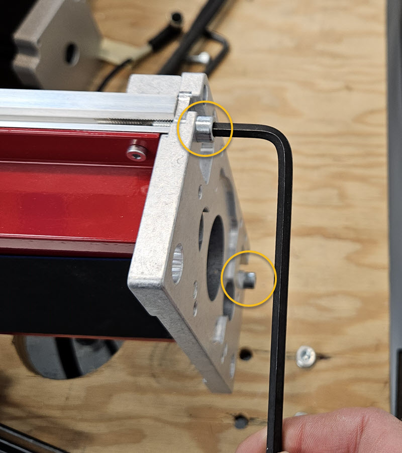
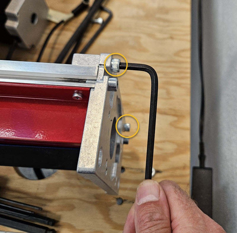
3.2.4


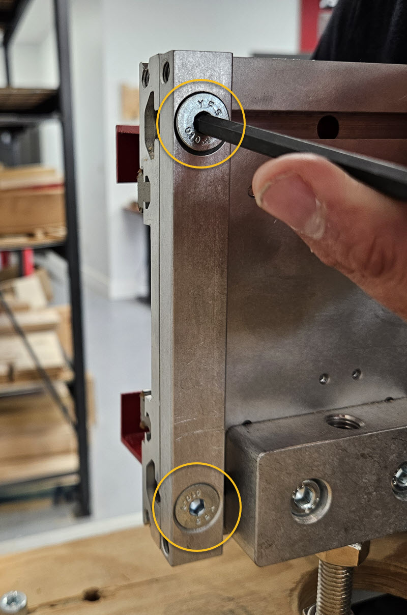
- To move the tip of the plate UP, tighten the upper set screw. To move the tip of the plate DOWN, tighten the lower set screw. Only adjust one set screw so that only one set screw is tight against the bearing block.
- Retighten the four screws previously loosened to lock the position.
3.2.5

- Replace the cover and two removed screws.
- Your Tool Height Setter is now installed and trammed.
4. Motor Control and Brake Cables
Parts List
| ID | QTY | Part/Description | Package Label |
|---|---|---|---|
1 | Servo Motor Hardware Kit | CRP320-00-XX-SRV-UP | |
A | 4 | M12 8-pin Motor Control Cable | |
B | 4 | Motor Cable Adapter | |
C | 1 | Z Axis Brake Cable | |
Tools List
| Requirement | Tool |
|---|---|
| Required | 3/32" Allen Wrench |
| Required | Flathead Screwdriver |
4.1 - Cable Installation
4.1.1
- To remove existing cables and prepare for routing new cables, it is recommended to open each cable track link using a small flathead screwdriver.
- Remove the existing motor cables.
4.1.2

| Motor | Color | Cable Length | Cable Routing Path |
|---|---|---|---|
| X | RED | 12' | Through table cable track |
| Z | BLUE | 20' | Through table cable track and gantry cable track |
- Attach a Motor Cable Adapter B to the end of each Motor Cable A.
- Connect each motor cable to their respective motor.
- Route the indicated motor cables as shown. The remaining two motor cables (Y1 and Y2) can be routed directly to your control box without going through cable track.
4.1.3

| Sensor | Color | Cable Routing Path |
|---|---|---|
| Z Brake | BLUE | Through gantry cable track and table cable track |
- Route the Z Axis Brake Cable C as indicated.
5. Servo Power Hub
Parts List
| ID | QTY | Part/Description | Package Label |
|---|---|---|---|
1 | Servo Motor Hardware Kit | CRP320-00-XX-SRV-UP | |
A | 1 | Servo Power Hub | |
B | 4 | M8 Roll-in T-nut | |
C | 4 | M8 x 14mm Socket Head Cap Screw | |
D | 1 | RD-24 Power Cable | |
Tools List
| Requirement | Tool |
|---|---|
| Required | 6mm Allen Wrench |
5.1 - Install Servo Power Hub
5.1.1

- Insert M8 Roll-in T-nuts B on the back of the gantry at the end closest to your table cable track.
- Attach the Servo Power Hub A to the back of the gantry using the M8 x 14mm Socket Head Cap Screws C.
5.1.2

- The Servo Power Hub should be oriented with the RD-24 panel mount facing the table cable track.
5.1.3

| Motor | Color | Cable Routing Path |
|---|---|---|
| X | RED | Directly to motor |
| Y1 | GREEN | Through table cable track then back to motor |
| Z | BLUE | Through gantry cable track |
| Y2 | YELLOW | Through table cable track then back to motor |
| RD-24 | BLACK | Through table cable track to control box |
| Refer to graphic in previous step for motor cable designations from Power Hub | ||
- Route each motor power cable to its respective motor as shown in the image.
- Connect each motor power cable to the motor.
- Route the RD-24 cable as shown. The other end will go to the control box.
6. EX Control Box Connections
Parts List
| ID | QTY | Part/Description | Package Label |
|---|---|---|---|
1 | EX Controller | EX Controller Kit | |
A | 1 | Emergency Stop Cable, 20' | Emergency Stop Kit |
B | 1 | Emergency Stop Switch | Emergency Stop Kit |
C | 1 | C13 Power Cable | EX Controller Kit |
D | 1 | Ethernet Cable, 10' | EX Controller Kit |
E | 1 | M12 Sensor Cable, 12' | Tool Height Setter Hardware |
F | 1 | M12 Splitter | EX Controller Kit |
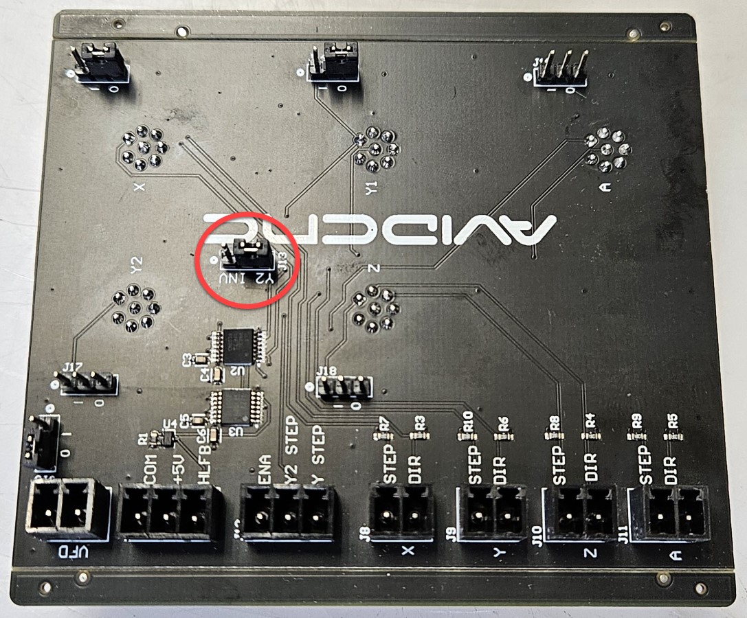
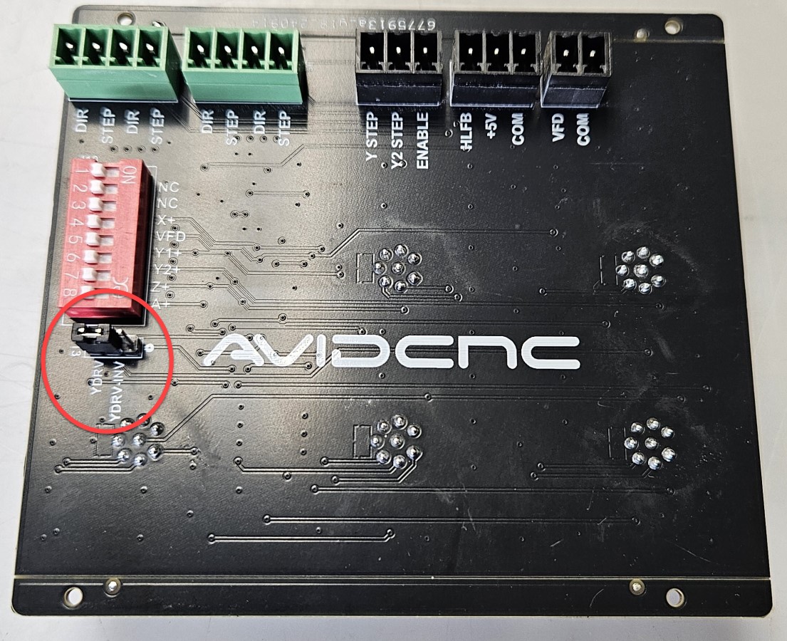
Assembly Note - Motor Direction
Prior to connecting your EX controller to your Benchtop PRO Machine, you will need to ensure a jumper on your servo card is correctly set so that the Y axis motors turn in the same direction.
- Locate the jumper on the inside of the I/O gland plate, behind the 8-pin M12 motor control cable panel mounts. Your servo card will look like one of the two images below.
- Verify that the jumper in is the position shown, covering the two pins nearest the "J13" label.
6.1.1
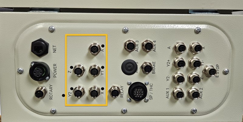
- Connect each motor control cable to the appropriate motor port.
Assembly Note
The A motor port is used for either a CNC Rotary Axis, or the U axis (second Z axis) on a dual-use machine.
6.1.2
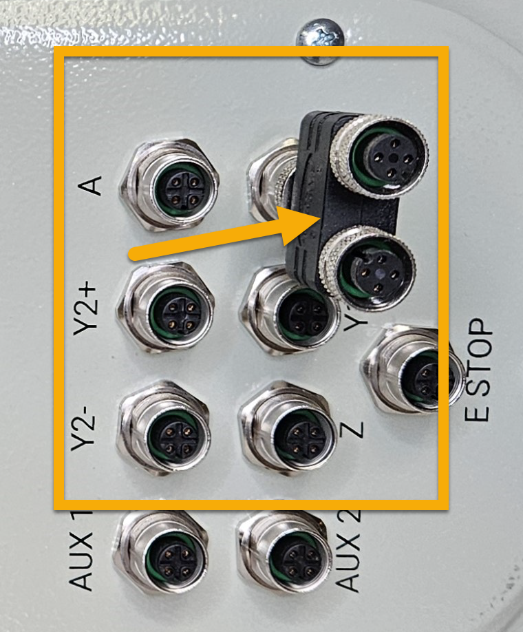
- Install the M12 Splitter F in the port labeled "X" on your controller.
6.1.3
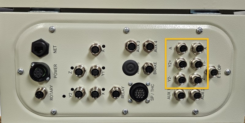
- Connect each sensor cable to the appropriate sensor port.
- The X- and X+ sensor cables will plug into the splitter installed in the previous step.
6.1.4
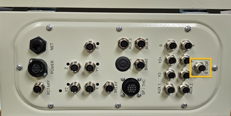
- Connect the Emergency Stop Cable, 20' A to the E Stop port.
- Connect the other end of this cable to the Emergency Stop Switch B .
6.1.5 - Spindle / Router Applications
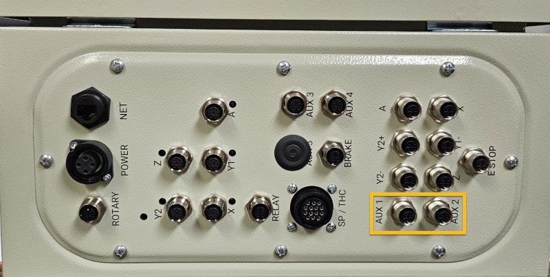
- Connect the Tool Height Setter to the Aux 2 port.
- Connect the optional Auto Z and Corner Finding Touch Plate to the Aux 1 port.
6.1.6 - Plasma Applications
6.1.6.1
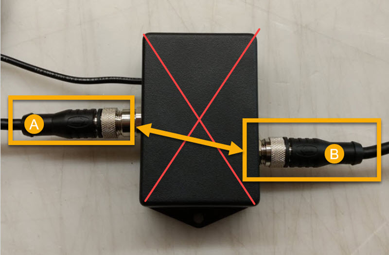
- Disconnect the existing sensor cables (A, B) from your Ohmic Protection Box.
- Connect the two sensor cables together.
Assembly Note
The Ohmic Protection Box is no longer used with EX controllers and may be removed.
6.1.6.2
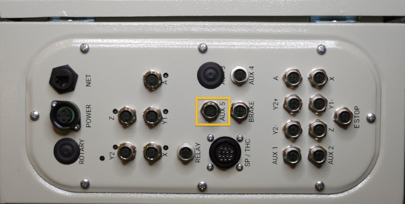
- Connect the free end of the extended Torch Mount cable directly to the Aux 5 port.
6.1.7 - Spindle / Plasma Applications
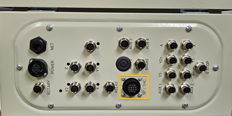
- Connect the existing SP/THC Cable to the SP/THC port.
- Depending on your current cutting method, this cable will be connected to either the Plug and Play Spindle / VFD Control Box, or your Hypertherm plasma power unit.
6.1.8
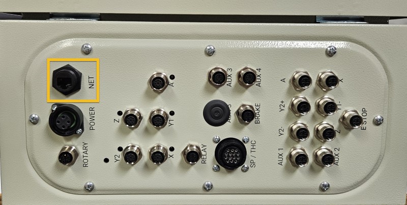
- Connect the Ethernet Cable, 10' D to the NET port.
- Connect the other end of the Ethernet cable to your control PC.
Ethernet Cable
Please ensure you're using the Ethernet cable included with the kit. The provided cable is shielded to reduce unwanted signal interference.
6.1.9
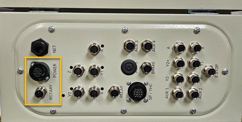
- Connect the RD-24 Power Cable to the Power port.
Assembly Note
The Rotary port is used for the servo motor power cable on a CNC Rotary Axis.
6.1.10
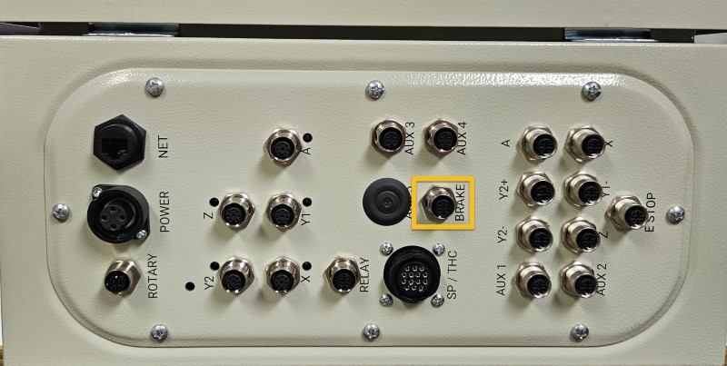
- Connect the Z-axis brake cable to the Brake port.
6.1.11
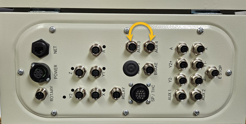
-
If you have a laser system, swap cables at the Aux 3 and Aux 4 ports.
For more information see the Laser Assembly Instructions