CNC12 Router Configuration Guide
Note
"DRO" is an acronym for the Digital Read Out. The DRO is the display on the CNC12 screen that tells the operator the current position of the machine.
Note
The text boxes in the Configuration Wizard will follow the units convention selected in the Machine Units dropdown unless otherwise specified.
Launch the Avid CNC Centroid Profile Manager
- With your Avid CNC EX Controller powered on and connected to your PC, open the Avid CNC Centroid Profile Manager.
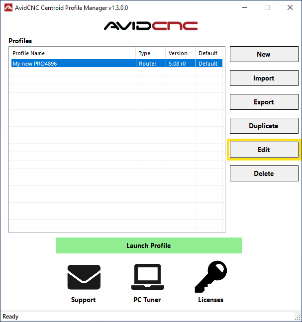
- Click on the profile you created earlier to highlight it, and then click the "Edit" button to launch CNC12 and open the Avid CNC Control Configuration Wizard.
Welcome Screen
The Welcome screen is the main landing screen for the Avid CNC Control Configuration Wizard.
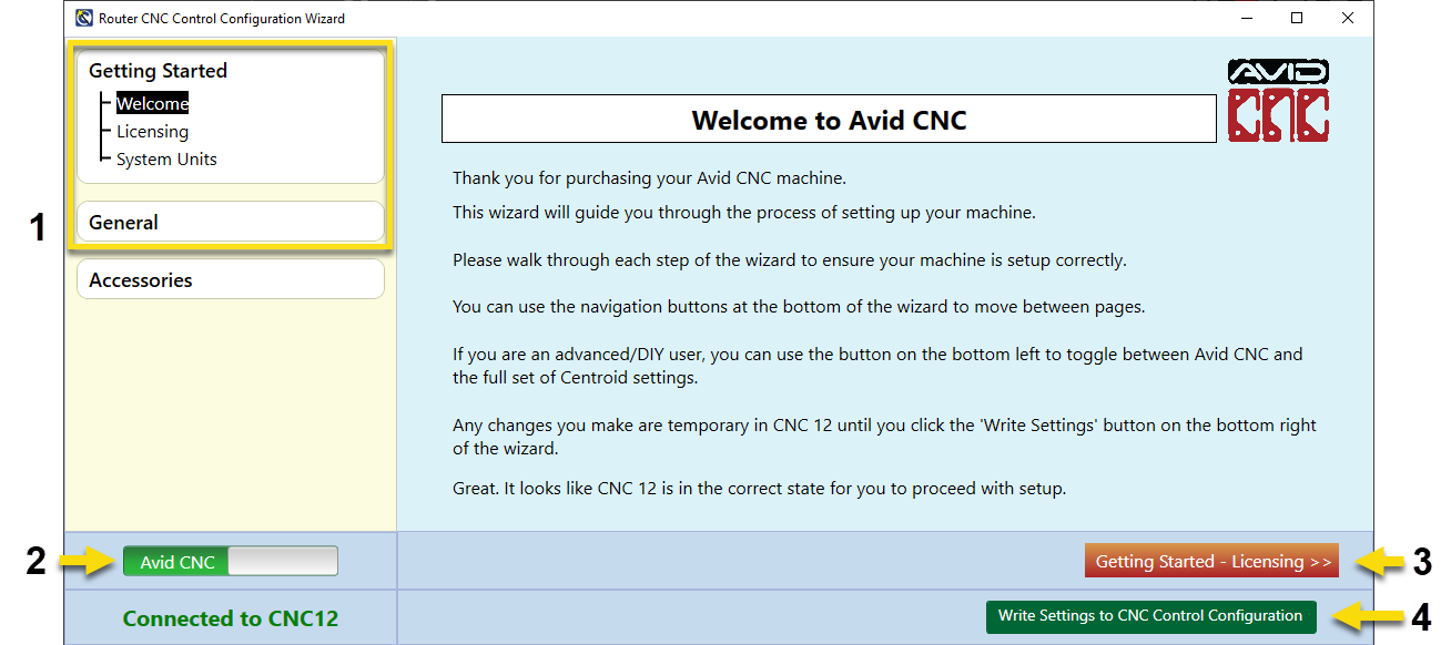
1. Table of Contents
A table of contents is shown on the left side of the CNC Control Configuration window. If you are setting up a machine for the first time we suggest using the Forward button (identified below) to page through and review each configuration menu.
The headers and sections in the table of contents can also be used as links to get back to a specific menu if you need to change a specific setting later.
2. Configuration Slider
The slider in the bottom left hand corner of the Wizard can be used to switch between the Avid CNC and Advanced configuration menus. Use the Avid CNC configuration options to set up your machine unless otherwise necessary.
3. Forward Button
The Forward button will advance to the next configuration screen, and will be labeled with the title of the next page of the wizard.
4. Write Settings Button
After completing all steps of the configuration instructions you'll click the Write Settings button to save the configuration and exit the configuration wizard. Changes to the configuration will not be saved until the Write Settings button is clicked.
Let's get started!
When you are ready, click the Forward button to advance to the next Configuration section. Continue using this button to advance through each menu as you follow these instructions.

Licensing
This screen provides instructions for licensing the software. The licensing process can be completed while the wizard is open. Simply minimize the Configuration Wizard window to access the CNC12 screen and perform the following licensing actions.
Note
Your license will be emailed to you by Support. If you have not yet received the license, or have not yet downloaded it from the email attachment, please feel free to continue with the rest of the configuration and come back to licensing later.

- Minimize the Wizard and, from the main screen of CNC12, click on Utility Menu (F7).

- From the Utility Menu, Click on Import License (F8).
- A File Browser window will open. Click on the license file to select it, and then click "Open" to install the license file.
- A confirmation message will display on the screen if the license is successfully imported. If you have any issues with licensing, please Contact Us.
Units Settings
This screen provides instructions for choosing the units used in CNC12.
By default, the units are set to Inches. If you wish to switch to Millimeters, please complete the configuration process before following the below steps.
If you try to minimize the configuration wizard window and set the units while the wizard is open, the settings will revert to default (Inches) when the configuration is saved.
Change Units (optional)
- From the main screen of CNC12, click on Utility Menu (F7).

- From the Utility Menu options, click on Advanced Config (F3).
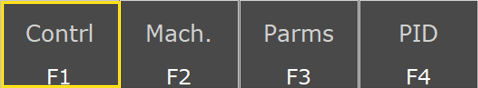
- From the Advanced Config menu, click on Contrl (F1).
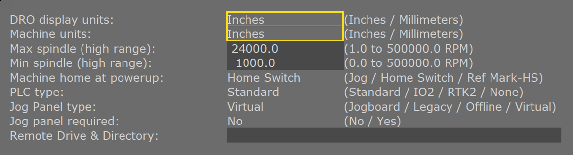
- Click the word "Inches" next to the DRO Display Units and the Machine Units once, and the setting will switch to "Millimeters".
- When you've set the units as desired, click Save (F10) to save the selections.
Note
It is recommended by Centroid to set the Machine units and the DRO display units so that they match.
Machine Setup
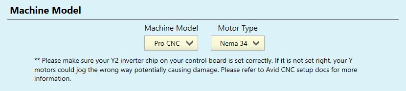
- Select your specific Machine Model and Motor Type using the dropdown menus.
Note for Servo Benchtop PRO Machines
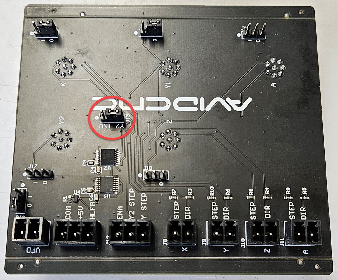
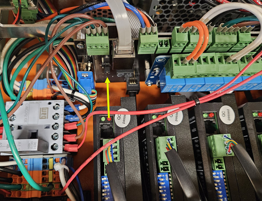
Prior to connecting your EX controller to your Benchtop PRO Machine, you will need to ensure a jumper on your servo card is correctly set so that the Y axis motors turn in the same direction.
- Locate the jumper on the inside of the I/O gland plate, behind the 8-pin M12 motor control cable panel mounts. Your servo card will look like one of the two images below.
- Verify that the jumper in is the position shown, covering the two pins nearest the "J13" label.
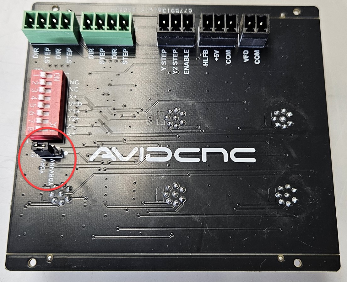
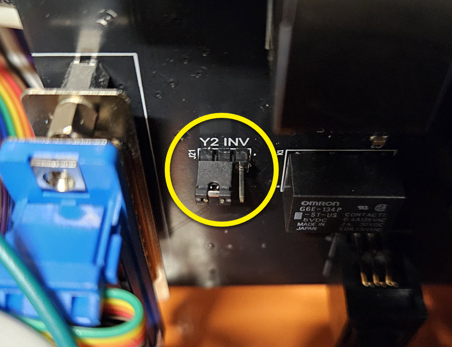
Note for Stepper Benchtop PRO Machines
Prior to connecting your EX controller to your Benchtop PRO Machine, you will need to ensure a jumper on your interconnect card is correctly set so that the Y axis motors turn in the same direction.
- Locate the jumper on the card near the middle of your controller, as shown in the first image.
- Verify that the jumper in is the position shown, covering the two pins nearest the "J21" label.
Machine Model:
- PRO CNC: Rack & Pinion Driven Router Systems
- PRO Plasma CNC: Rack & Pinion Driven Plasma Systems
- Benchtop PRO: Ballscrew Driven Router Systems
Motor Type:
- NEMA 34: 1/2" Shaft Motors with XLR cables
- NEMA 23: 3/8" Shaft Motors with DB9 cables
- Servo: Closed loop motors, 2 cables per motor

- Select the nominal size of your machine's working area using the drop-down menus. The Width, Length, and Height selected in the Machine Dimensions section will automatically set the Soft Limits to the correct default settings for your Machine Type.
-
The Height (Z Axis) refers to the maximum Z axis travel distance. The Gantry Height does not need to be configured using the wizard.
Configuration Note
Check the details listed on the invoice for your order to confirm the correct Width, Length, and Z-axis travel for your specific machine kit.
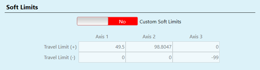
- Soft Limits: Fine adjustments to the available working area can be made by adjusting the soft limits settings. The Custom Soft Limits slider will enable or disable the Custom Soft Limits settings. Feel free to leave these values at the default for now, they can always be adjusted later as needed.

-
Prevent Spoilboard Dig In: (Router Only) Enable this setting to restrict Z-axis travel in addition to the soft limits, and prevent the bit from cutting into the spoilboard. If enabled, the end of the bit will stay above the Work Surface height at all times when G-code is running. This function will not limit the Z axis travel when jogging.
This is a global setting, set for the entire working area. In some cases an operator may want the tool to go below the work surface.
Motor & Jog
Rotary Setup Note
If installing an Avid CNC Rotary Axis, you will set the Axis 4 motor tuning settings on the Rotary page in Step 12 of these instructions.
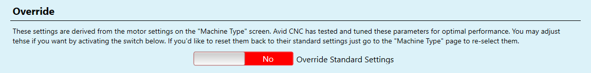
- Override Slider: If needed, use the Override slider to unlock and adjust the motor and jog settings. Only do this if you are sure of how the changes will affect performance and have a specific reason to do so.
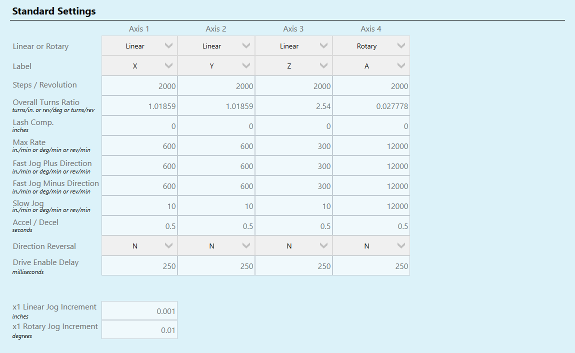
- Standard Settings: When the Override slider is set to "Yes", the operator can make adjustments to the default settings. If you have any questions about these values, or need assistance adjusting them, please Contact Us.
Home and Park

- Square Gantry: Select this option for all Avid CNC Machine Kits equipped with a Proximity Sensor Kit. When selected, the system will use both Y axis motors and sensors to square up the two sides of the gantry during homing.
- Do Not Square Gantry: Only select this option if installing Avid CNC Centroid electronics on a DIY or Retrofit machine that only has one Y axis motor and homing sensor.
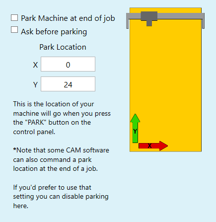
Park Settings:
- Park Machine at End of Job: If selected, the machine will raise the Z-axis and move to the park location at the end of each G-code cycle.
- Ask Before Parking: If selected the system will prompt the operator to click "Cycle Start" after homing is complete, and will wait for the button to be clicked/pressed before moving the machine to the park location.
- Park Location: Enter the location the machine will move to when commanded to park. This position needs to fall within the limits of the machine's travel, or in other words, inside the soft limits.
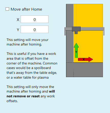
- Move After Home: If the checkbox is selected, the axes will move to the indicated position after the machine homes successfully. The software will always ask for additional user confirmation before moving to the "Move After Home" location.
Cutting Tools
Cutting Tool Selector:
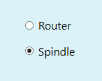
- Router: Choose this option if installing a router or other AC tool as the main cutting tool for the machine. An additional Auxiliary Power Relay is required if using a Router as the cutting tool. The system will use the accessory relay to turn the router on or off if this option is selected.
- Spindle: Choose this option if installing a Plug and Play Spindle/VFD kit or a DIY Spindle that uses a Variable Frequency Drive (VFD). The system will send signals through the SP/THC cable to control the cutting tool if this option is selected.
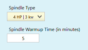
Spindle Type and Warmup:
- Spindle Type: Select your Plug and Play Spindle from the drop down menu to automatically configure the minimum and maximum spindle speed for your setup. If installing a DIY spindle, select Generic to unlock the custom RPM range.
- Spindle Warmup: If using a Plug and Play Spindle/VFD kit, the spindle warm-up routine will be specific to the spindle, and will feature a number of warm-up cycles with pauses in-between. If using a DIY or 3rd party spindle, the system will run one warm-up cycle for the amount of time set here.
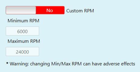
- Custom RPM: The default Minimum RPM and Maximum RPM will be set based on the Spindle Type selected. Use the Custom RPM slider to enable changes to the default settings.
Laser Setup Note
If installing a laser system on the machine, the settings will be configured on the Laser page in section 11 of this guide.
Warnings / Defaults
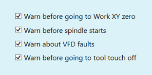
Warning Selectors:
These checkboxes configure how CNC12 will react to events or conditions that the user might want advance warning about. Select the checkboxes as needed per your preference.
- Warn Before Going to Work XY Zero: The Go To XY button will drive the machine in a straight line from its current position to the X0/Y0 position. The machine travels at the fast jog rate when doing so, and we suggest leaving this box checked to avoid unexpected movement caused by accidental button presses.
- Warn before Spindle Starts: Checking this box will cause the system to require additional confirmation from the operator before the spindle will start spinning. This will be required whenever the spindle starts, either during a G-code cycle or when using the MDI.
- Warn about VFD Faults: If this box is checked the system will alert the user when the spindle is in a fault state. Fault states include the spindle not being powered on, a stall condition, or any other electrical failure within the VFD. When the spindle is in a fault state the machine will not be able to be homed or moved. If a fault state occurs during a job, motion will stop and a warning will be displayed.
- On servo systems the VFD fault signal is tied into the Drive Fault signal. In the event of a spindle fault, "VFD/Drive fault" will be displayed on screen and the machine will be in a fault state. If you wish to bypass VFD faults you will need to use the dip switches or jumpers (based on your model) on the servo board in the control box and NOT this option. More information is available in the EX Controller Technical Manual.
- Warn before warming up spindle: This can be helpful as a reminder to remove any tooling or collets from the spindle before starting the warm-up routine. To get the most longevity from your Plug and Play Spindle, make sure to run the warm-up routine with the spindle nose bare (no collet or tool mounted).
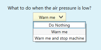
Low Air Pressure Warning:
This drop down will configure how the system reacts to low air pressure. You might want a warning if you are installing the Avid CNC Deployable Laser System, which features an air pressure sensor. If your connected pneumatic accessory does not feature an air pressure sensor, set it to "Do Nothing".
- Do Nothing: CNC12 will not respond to the state of the “Air Pressure OK” input and the user will be responsible for ensuring any connected pneumatic accessories have good air pressure before starting a job.
- Warn Me: CNC12 will warn the user with an on-screen message that the air pressure is low, but will still allow the system to function.
- Warn me and Stop machine: CNC12 will warn the user with an on-screen message that the air pressure is low, and will not let any operations run (including homing and jogging) until the air pressure is restored to the proper level. Select this operation only if a lack of air pressure will cause an unsafe condition for the operator or the machine.
Laser Setup Note
A low air pressure warning specific to Laser operations will be configured later on in this guide. The settings configured here will not prevent laser-specific warnings from appearing.
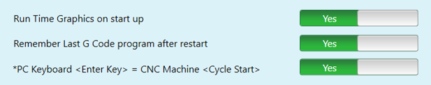
Run Time Graphics on Startup: If this slider is ON, the CNC12 screen will show a graphical representation of the job when the Cycle Start button is pressed. If it is set to "Off", the screen will default to displaying a scrolling list of G-code commands as they are run. During an active job, the user can cycle between the modes as needed.
Remember Last G-code Program after Restart: If this slider is in the On position, the last used G-code file will be stored in the control when the system is powered off. If it is on the Off position, a placeholder "NO_JOB_LOADED" placeholder file will be loaded into the control at startup.
*PC Keyboard <Enter Key> = CNC Machine <Cycle Start>: Set this slider to the On position to turn the Enter key into a hotkey for the Cycle Start key.
Relay Behavior
Note
Controlling AC accessories such as a lamp, fan, or dust collector using the two relay outputs requires the purchase of the optional Auxiliary Power Relay.
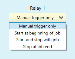
These selections will set the behavior of the relays, which are optional electronically controlled switches connected to and triggered by the CNC Controller.
- Manual Trigger Only: When this is selected the operator will control the relay. The system will still respond to relay on/off commands present in the G-code.
- Start at Beginning of Job: When this is selected the relay will turn on automatically at the start of a G-code cycle. The system will still respond to relay on/off commands present in the G-code. The relay will stay on until it is turned off.
- Start and Stop With Job: When this is selected the relay will turn on and off when the G-code cycle starts and stops. The system will also respond to relay on/off commands present in the G-code.
- Stop at Job End: When this is selected the relay will automatically turn off at the end of the job, but the operator will be responsible for turning it on before the job starts. The system will still respond to relay on/off commands present in the G-code.
Operator Position
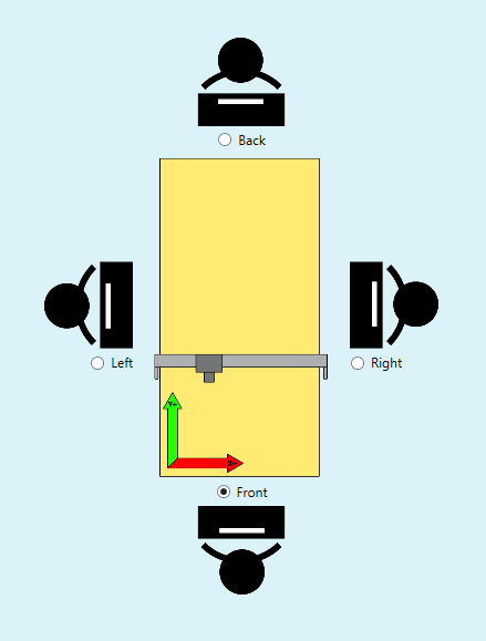
- Position Selector: Select the option that best fits your perspective as you sit at the monitor and keyboard and face the machine.
The keyboard jog keys and on-screen buttons will be rotated based on your selection, but the coordinate system of the machine will always align with the green and red arrows shown in the diagram.
For example, an operator using the "Right" position would jog in X- when pressing the Up arrow key on the keyboard, and an operator in the "Front" operator position would jog in Y+ when pressing the Up arrow key on the keyboard.

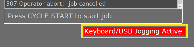
- Keyboard Jog Slider: If this slider is set to "No", the operator will need to press ALT + J on the keyboard to enable keyboard jogging. If set to "Yes", keyboard jogging will be enabled by default.
Note
When keyboard jogging is enabled, the indicator message below will be displayed on the CNC12 screen:
Laser
If using the Avid CNC Deployable Laser System, the selections in the general section will apply all the necessary settings.
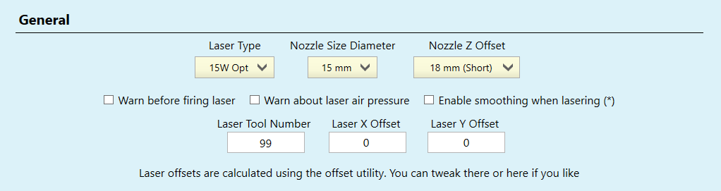
- Laser Type: Choose from none, 15W Opt, or Custom. Selecting Custom will unlock the Custom Nozzle and PWM Setup sections.
- Nozzle Size Diameter: This will be set to 15mm unless the Custom Nozzle settings are activated.
- Nozzle Z Offset: This dropdown is used to quickly configure the Z offset for 15W OPT systems. If using a custom laser, you'll set this offset in the Custom Nozzle settings instead.
- Warn Before Firing Laser: This option is selected by default and highly recommended. The operator and any spectators will need proper eye protection during laser operations. One pair is included with the purchase of Avid CNC Deployable Laser Systems. Please reach out using our Contact Us form to purchase extra eye protection if needed.
- Warn About Low Air Pressure: When this checkbox is selected, CNC12 will warn the operator if air pressure is low at the time that the laser is deployed. If using a laser system that features a pneumatic deployment system, we suggest checking this box. The setting previously configured in the "Warnings" section will not prevent this warning from appearing if the air pressure is low and this option is selected.
- Enable Smoothing When Lasering: Unless required for a specific reason, we advise against enabling smoothing during laser operations in most cases. Enabling smoothing will increase the cycle time of laser operations.
- Laser Tool Number: When this tool number is active, the deployment system will extend. When a different tool is called, the deployment system will retract.
- Laser Offsets: When using the deployable laser system, the offsets will be set automatically during the Laser X/Y Offset touch-off routine. The offsets can be adjusted manually here as well.
If the Laser Type is set to "Custom", these settings will be editable.

- Custom Nozzle Size: Set to "Yes" to edit the custom diameter and Z offset.
- Diameter (inches): The diameter of the laser nozzle, used by the Laser X/Y Offset utility and Touch Plate macros to correctly set offsets for laser operations.
- Z Offset (Inches): The distance of the focal point of the laser from the tip of the nozzle, used to set the tool offset for the focal point of the laser when using the Touch Plate or Calibrate Laser macro with the laser nozzle.
If the Laser Type is set to "Custom", these settings will be editable.
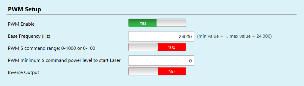
Caution
Configuring the PWM settings incorrectly can cause damage to the laser equipment!
- PWM Enable: This slider will need to be set to "Yes" if your laser is driven using a PWM signal.
- Base Frequency: Configure this setting per your laser manufacturer's recommendation.
- PWM S command range: Establishes the range of values used to define the laser power in G-code. Set the range to match the values output by your CAM software and post processor.
- Inverse Output: Use this setting if your custom laser setup needs an active low signal to activate the laser.
Rotary / Dual Use
The options on this screen configure the behavior of the optional 5th driver in a 5-drive EX CNC Controller. If you have a 4-drive (3-axis) EX CNC controller, leave this option set to default and move on to the next section in the guide.
3 Axis with Rotary
- Rotary Installed: If your EX controller is configured to use Servo motors, make sure to set the enable jumper for the 5th driver. More information is available in the EX Controller Technical Manual.
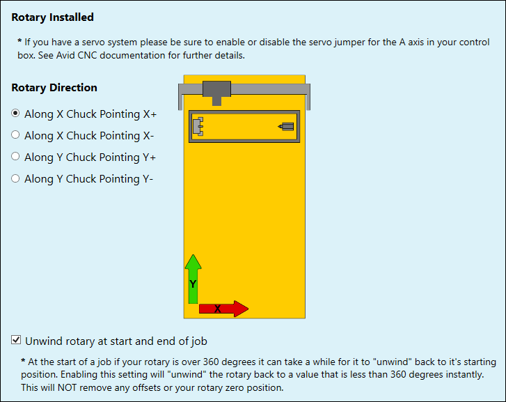
- Rotary Direction: The rotary can be installed in a few different positions and orientations depending on your application. Select the option that best fits your installation using the diagram for reference.
- Unwind Rotary at Start and End of Job: Selecting this option is a good idea if your work involves rotary operations that use a spiral machining strategy. When this checkbox is selected, the DRO will only display degree values up to 360deg. When the axis passes 360deg of rotation, the DRO will display an R number indicating the number of full rotations, with the partial rotation displayed next to this in degrees. CNC12 will clear the full rotations automatically (without physical rotation of the A axis) and the system will only need to move the remaining partial rotation when moving back to home at the end of the job.
Dual Z With Rotary - Rotary Active
Note
The EX CNC Controller must be fully powered off when disconnecting or re-connecting motor cables. Failure to do so can cause permanent damage to the motor drivers. After saving the configuration, make sure to power cycle the controller if not already directed and swap the motor cables when the system is powered off.
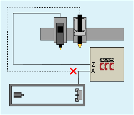
The 5-drive EX controller can be configured to drive a dual-purpose cutting tool or a rotary, but not at the same time. If you have a Dual Z machine with a rotary installed, you will need to change this setting to the desired function before re-configuring the cable connections.
In this scenario the Rotary will connect to the A port on the CNC Controller, and the second Z axis will be disconnected. The second Z axis will remain where it was last parked before switching to this configuration.
- Rotary Installed: If your EX controller is configured to use Servo motors, make sure to set the enable jumper for the 5th driver. More information is available in the EX Controller Technical Manual
- Rotary Direction: The rotary can be installed in a few different positions and orientations depending on your application. Select the option that best fits your installation using the diagram for reference.
- Unwind Rotary at Start and End of Job: Selecting this option is a good idea if your work involves rotary operations that use a spiral machining strategy. When this checkbox is selected, the DRO will only display degree values up to 360deg. When the axis passes 360deg of rotation, the DRO will display an R number indicating the number of full rotations, with the partial rotation displayed next to this in degrees. CNC12 will clear the full rotations automatically (without physical rotation of the A axis) and the system will only need to move the remaining partial rotation when moving back to home at the end of the job.
Dual Z With Rotary - Second Z Active
Note
The EX CNC Controller must be fully powered off when disconnecting or re-connecting motor cables. Failure to do so can cause permanent damage to the motor drivers. After saving the configuration, make sure to power cycle the controller if not already directed and swap the motor cables when the system is powered off.
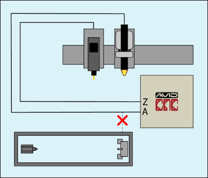
The 5-drive EX controller can be configured to drive a dual-purpose cutting tool or a rotary, but not at the same time. If you have a Dual Z machine with a rotary installed, you will need to change this setting to the desired function before re-configuring the cable connections.
In this scenario the second Z axis will connect to the A port on the CNC Controller, and the Rotary will be disconnected. The Rotary will remain where it was last parked before switching to this configuration.
Probe
Note
These settings are used to configure 3rd-party spindle probes, used to measure the position of a workpiece, vise, or fixture. These probes are different from the Tool Height Setter or the Auto-Z and Corner Finding Touchplate. Compatible spindle probes can be seen on the Centroid webstore.
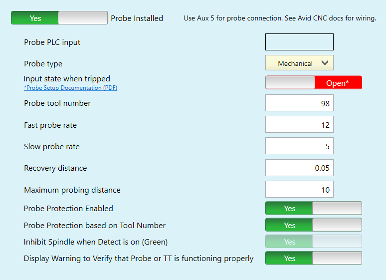
- Probe PLC input: This box is "blank" as the probe is required to be connected to Aux 5.
- Probe type: Select the type of probe you are using from the drop down list. If you are unsure of the probe type, check with the manufacturer of the probe.
- Input state when tripped: Slide the slider to Closed or Open depending on how your specific probe is configured. Check with the manufacturer of your specific probe to know how it is configured.
- Probe tool number: The tool number associated with the probe. Used to toggle between probe jog rate and the main jog rate when the "Probe Protection Based on Tool Number" slider is set to "Yes".
- Fast probe rate: The speed of the axes when traveling between slow measurement moves.
- Slow probe rate: The speed of the axes after initial touchoff, used when measuring the actual value.
- Recovery distance: The distance that the probe backs off after a successful touchoff before it moves to the next location in the probing routine.
- Maximum probing distance: If the axes travel farther than this distance during the probing routine, the system will output an error and stop the routine.
- Probe Protection Enabled: If Probe Protection is enabled, the system will switch to the probe jog rate whenever the probe is detected. CNC12 will detect the probe and turn on probe protection based on either the tool number or an additional input you've set up for this purpose.
- Probe Protection based on Tool Number: If this slider is set to "Yes", the jog rate will automatically switch to the Probe Slow Jog rate when the Probe Tool Number is set as the current tool during a tool change.
- Inhibit Spindle when Detect is on (Green): Disables the spindle when Probe Protection is active. If your probe is a wired probe, this can help prevent the cable from being accidentally damaged.
- Display Warning to Verify that Probe or TT is functioning properly: If this is set to "Yes", a dialog box will appear before the probing routine begins prompting the user to touch the probe and check that it is working.
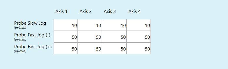
- Probe Jog Rate Table: This table can be used to adjust the probe jog rate. The Probe Fast Jog rate is the jog rate that is set when the Probe Protection is enabled and active. If the probe is tripped while jogging, the system will switch to the Probe Slow Jog rate.
Touch Plate
General Configuration:
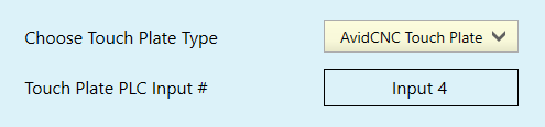
- Choose Touch Plate Type: Select the type of touch plate you will use with the machine from the dropdown menu. Individual settings for each different touch plate type are listed below.
- Touch Plate PLC Input #: The input for the Touch Plate is fixed as Input 4.
Avid CNC Touch Plate:
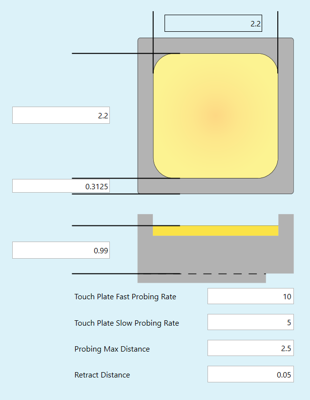
- Touch Plate Dimensions: The dimensions of the touch plate are editable via the text boxes in the touch plate diagram. Only edit these as needed, and in general you should not need to edit the dimensions for the Avid CNC touch plate.
- Touch Plate Fast Probing Rate: The feed rate used for travel moves during the touch plate routine.
- Touch Plate Slow Probing Rate: The feed rate used for measuring moves during the touch plate routine.
- Probing Max Distance: If any axis travels farther than this distance during the probing routine, the user will receive an error and the routine will cancel.
- Retract Distance: The distance that the bit will retract away from the brass plate before probing in the X or Y axis. This happens after the initial Z axis touch-off.
Surface Plate:
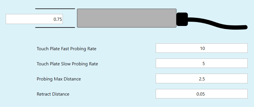
- Touch Plate Dimensions: The thickness of the touch plate is editable via the text box in the touch plate diagram.
- Touch Plate Fast Probing Rate: The feed rate used for travel moves during the touch plate routine.
- Touch Plate Slow Probing Rate: The feed rate used for measuring moves during the touch plate routine.
- Probing Max Distance: If any axis travels farther than this distance during the probing routine, the user will receive an error and the routine will cancel.
- Retract Distance: The distance that the bit will retract away from the brass plate before probing in the X or Y axis. This happens after the initial Z axis touch-off.
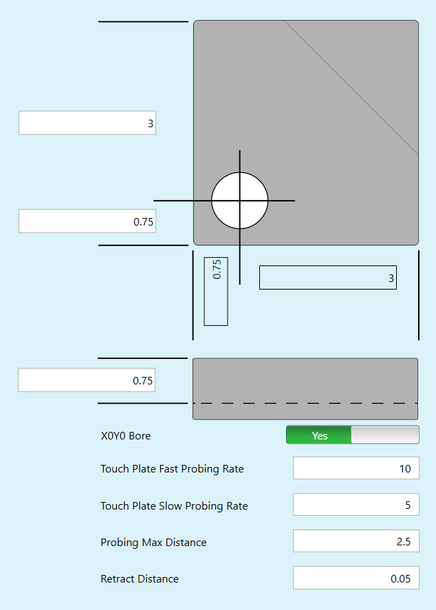
Define Your Own:
- Touch Plate Dimensions: The dimensions of the touch plate are editable via the text boxes in the touch plate diagram.
- X0Y0 Bore: Set to "Yes" if your plate includes the X/Y Zero borehole shown in the diagram.
- Touch Plate Fast Probing Rate: The feed rate used for travel moves during the touch plate routine.
- Touch Plate Slow Probing Rate: The feed rate used for measuring moves during the touch plate routine.
- Probing Max Distance: If any axis travels farther than this distance during the probing routine, the user will receive an error and the routine will cancel.
- Retract Distance: The distance that the bit will retract away from the brass plate before probing in the X or Y axis. This happens after the initial Z axis touch-off.
Wireless MPG
In addition to the onscreen buttons and keyboard shortcuts, MPGs (Manual Pulse Generators) are handheld devices that allow convenient and precise control of the machine, bringing the operator closer to the workpiece during setup tasks and testing.
Please Note
Use of a Centroid MPG requires a PRO, Ultimate, or Ultimate Plus license for CNC12.
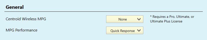
Centroid Wireless MPG: Select the option that matches your MPG.
- CWP-4: An older model of the Centroid MPG which is compatible with the Avid CNC EX Controller electronics.
- WMPG-4: Configured for use with Plasma machines, currently available product.
- WMPG-6: Configured for use with Routing machines, currently available product.
MPG Performance: Choose the response time for the scroll wheel on the MPG. This will change how it "feels" to jog using the MPG.
- Try jogging the machine using each different setting to find the one that works best for your application.
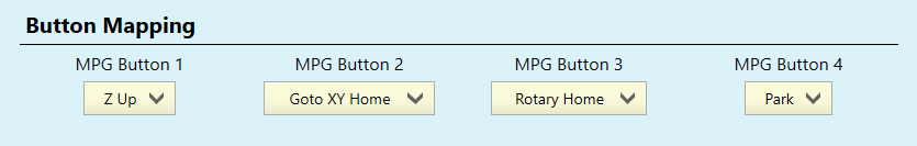
The routing-compatible Centroid WMPG-6 features four programmable Macro buttons. The function of these buttons is user configurable via the dropdowns shown above. A brief description of each macro option is provided below.
- Z Up: Drives the Z axis to the top of its travel at a fast jog rate.
- Z to Plate: Probes the Z axis to set Work Coordinate System offset for Z only using the Touch Plate.
- Park: Drives the X and Y axes from their current position to the Park position.
- Rotary Home: Homes the Rotary Axis only, other axes will stay in position.
- Relay 1 On/Off: Turns on or off the accessory connected to the Relay 1 output of the Relay Box Accessory.
- Relay 2 On/Off: Turns on or off the accessory connected to the Relay 2 output of the Relay Box Accessory.
- GoTo XY Zero: Drives the axes to center the tool on the point in the active WCS where the DROs read "0.00".
- Custom: Users can set up a custom macro that can be triggered by the buttons on the MPG. When you set the button mapping to "Custom" and press the associated macro button, a message will appear on screen that lists the location of the macro so you can find and edit it.
Save Settings

When you are ready to save the changes you've made to the profile, click the "Write Settings" button to continue.
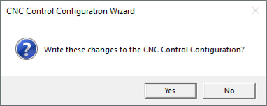
The software will ask for confirmation before writing the settings to the CNC Control Configuration, click "Yes" to continue.
Please Note
Restarting the CNC12 software is required whenever new settings are saved. In some cases, the controller will also need to be restarted. The different pop-up messages below will be displayed after saving new settings using the wizard, and will let you know if one or both are required.
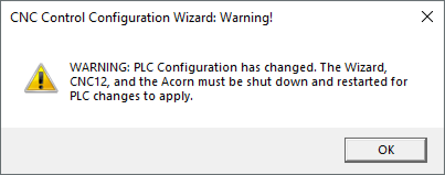
If the PLC Configuration has changed: This window will be displayed if changes were made to the internal settings of the CNC Controller.
- Click "OK" to continue.
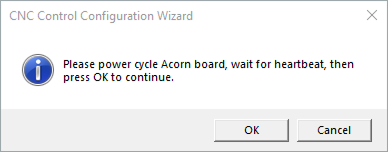
- When this message appears, turn off the CNC Controller and wait 5 seconds, then turn it back on again. Wait another 5 seconds before clicking "OK".
- After clicking "OK", the Avid CNC Control Configuration Wizard will close and CNC12 will open into the newly edited profile.
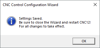
If the PLC Configuration has not changed: This window will be displayed if the changes only modified the settings within the CNC12 software.
- Click "OK" to continue. The Avid CNC Control Configuration Wizard and the CNC12 software will need to be closed manually.
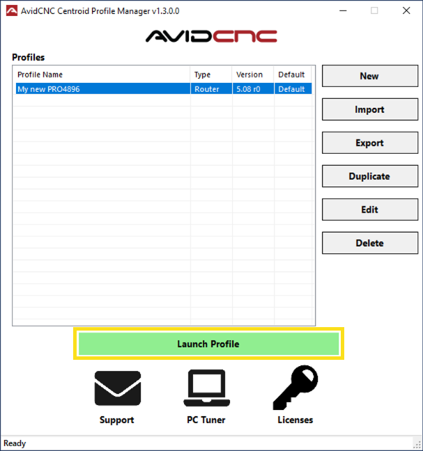
With your newly edited profile selected, click the "Launch Profile" button to restart CNC12 and open the newly edited profile.
Once CNC12 is configured, you may move on to the CNC12 Users Guide.