Peripherals
Adding Additional IO (non-Plasma Systems)
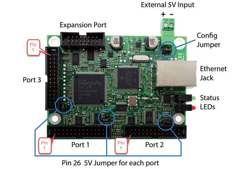
If the existing IO (both the M12 sensor inputs and the screw terminals on the CRP850-00E-F01 Breakout Board) are not enough for your application, it is possible to add an additional ribbon cable and breakout board to the Ethernet Smoothstepper (ESS). Port 3 on the ESS is a standard 26-pin low profile male parallel port connector. Connecting this to an external breakout board will expose 4 outputs, 8 inputs, and 5 bi-directional pins. You will need at minimum:
- A ribbon cable with appropriate connectors. To power the breakout board from the ESS a 26-pin connector on both ends is required.
- A breakout board with appropriate connectors and opto-isolation for the input signals.
For complete information see Warp9's documentation: warp9td.com/index.php/documentation/doc-ess
Adding Z Axis Electromagnetic Brake Output
The 24.2 version of the PRO Ballscrew Z axis features an electromagnetic holding brake that requires 24VDC to release. These instructions cover upgrading a CRP800-00E controller with the necessary power supply and connector.
Safety Note
Ensure your CNC control box is powered off with the power cable disconnected from the box.
Parts
| ID | QTY | Part Number - Description |
|---|---|---|
| 1 | CRP800-00E-ZUP-24.2 - Kit, CRP800-00E Retrofit, Z Axis Brake | |
| A | 1 | CRP850-31E - Wire Harness, Brake Retrofit |
| B | 2 | FW-625-SHIM - Flat Washer, 5/8" ID x 1-1/4" OD |
Tools
- 17mm open end wrench
- 18mm open end wrench
- Small flathead screwdriver
- Phillips Head PH2 screwdriver
1 - Remove the Motor Disable Switch
1.1
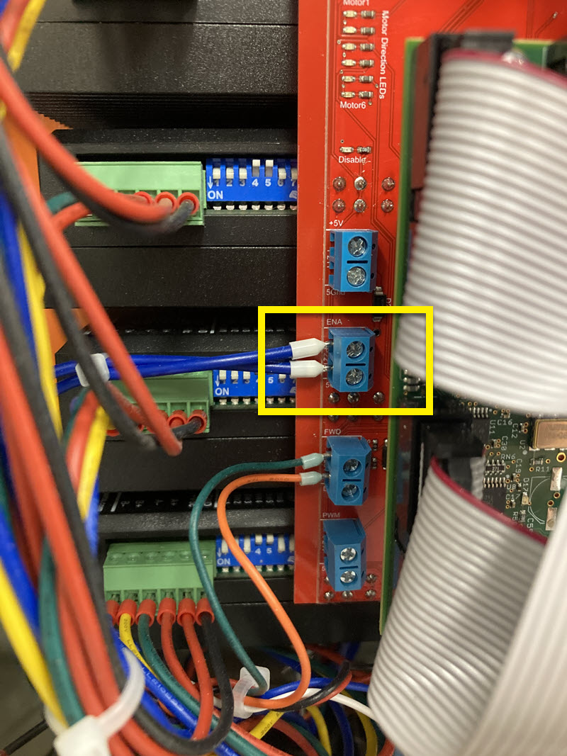
- Locate and remove the Enable wires from the CRP850-00E breakout board.
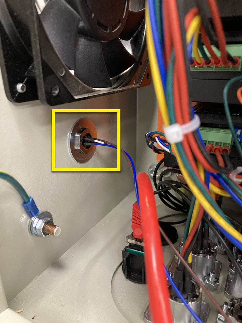
1.2 - Remove the Disable Switch
1.2.1
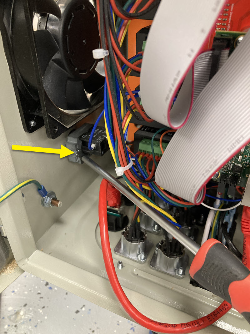
- Inside the enclosure, loosen the accessible Phillips head screw until the switch is loose.
- Rotate the switch body to access the second Phillips head screw and loosen it.
1.2.2
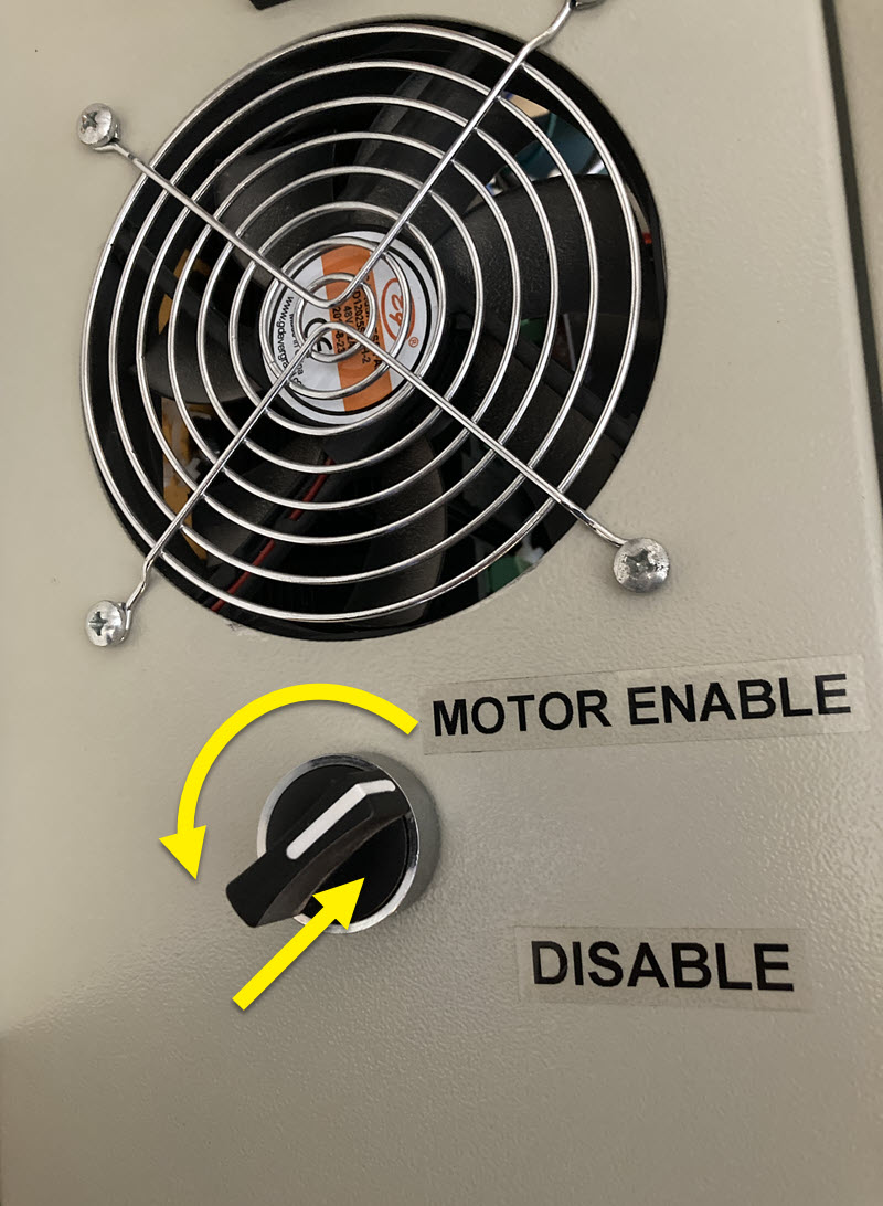
- Remove the switch exterior by pushing in and turning.
- Remove the switch body and wiring from the controller.
2 - Install the 24V Power Supply
Revision Note
These instructions show a 20.1+ revision controller. For older CRP800-00E controllers the steps are the same, but component locations are different. See step 2.2.2 for locations.
2.1 - Connect APV to Terminal Blocks
2.1.1
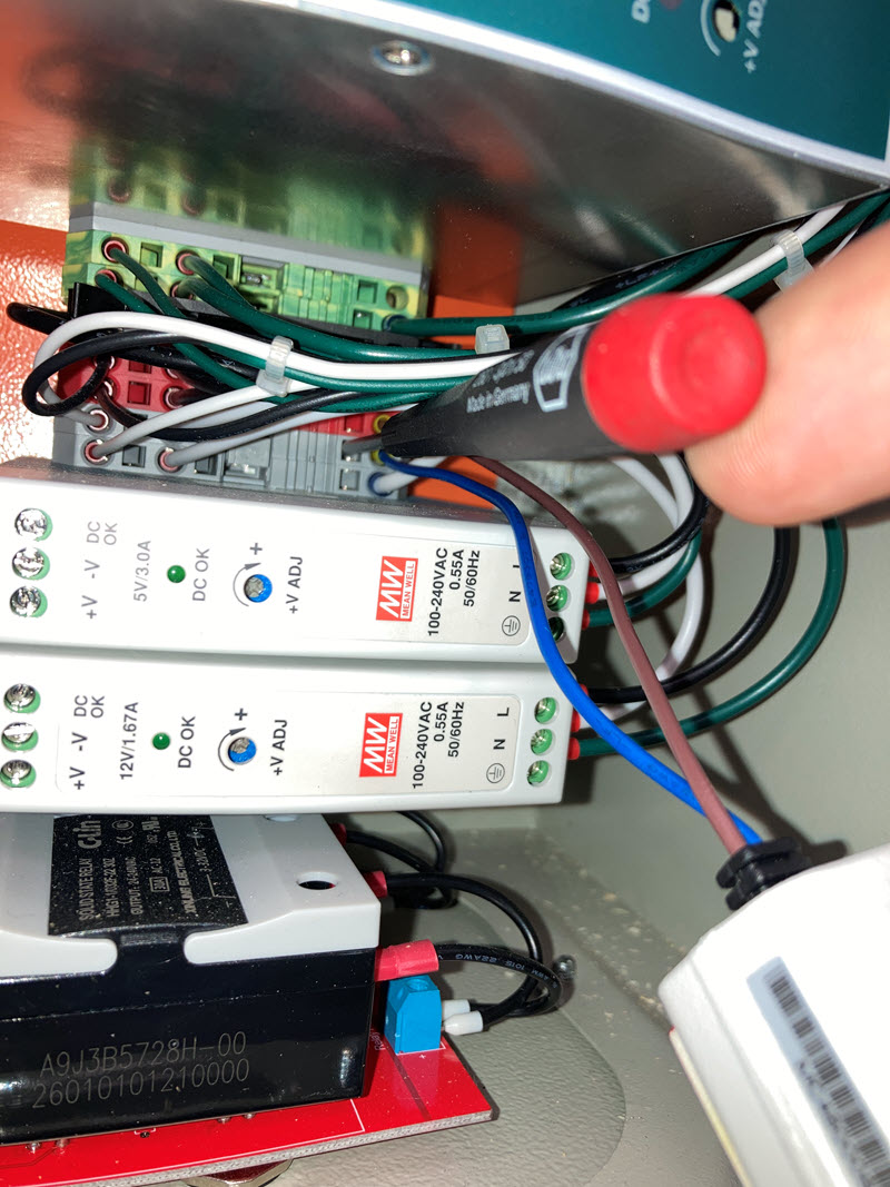
- Use a flathead screwdriver as shown to insert the ferruled wires into terminal blocks. Insert the screwdriver into a square opening next to the open round terminal position. Push the top of the screwdriver away from the terminal position to open. Insert the ferrule.
2.1.2
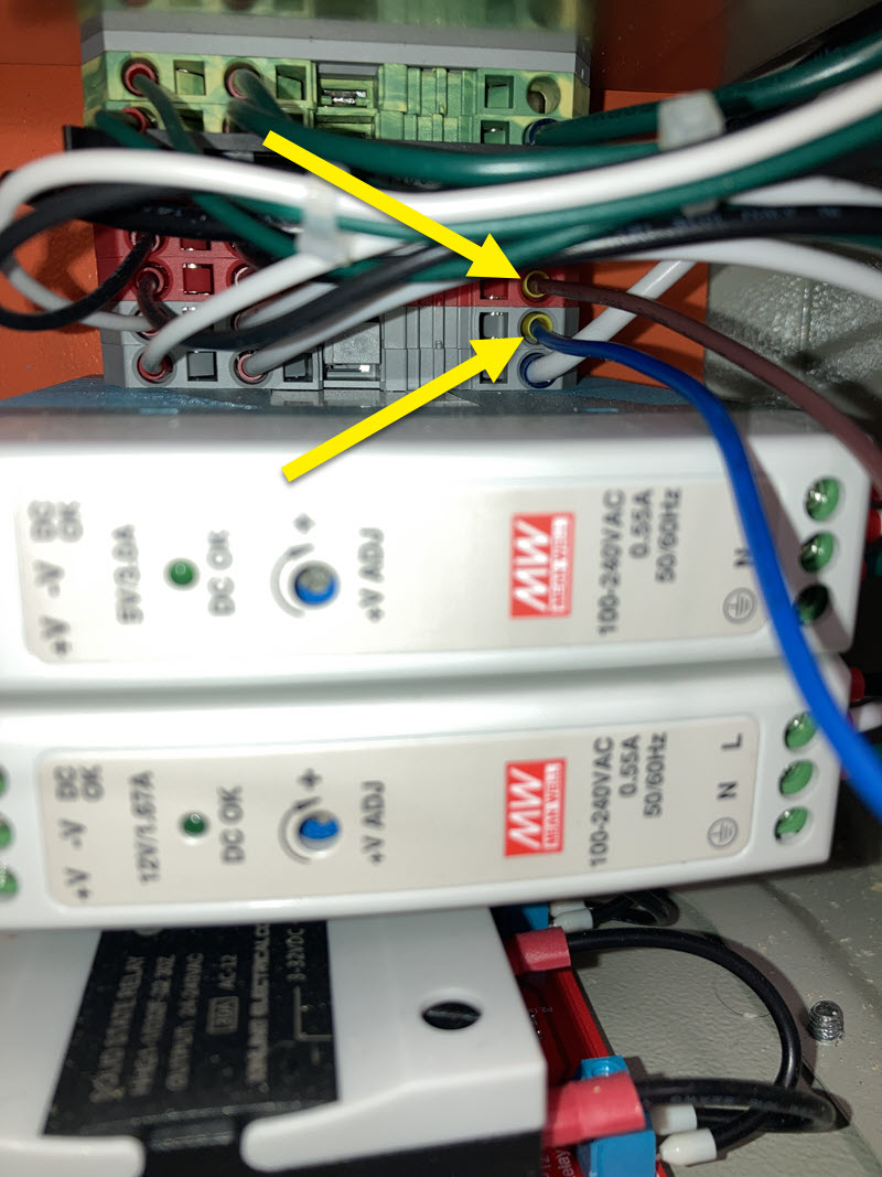
- Connect the ferruled Brown wire to an open Red terminal block.
- Connect the ferruled Blue wire to an open Gray terminal block.
2.2 - Mount the APV
2.2.1
Revision Note
For 20.1 and newer controllers. For older CRP800-00E controllers, skip to 2.2.2.
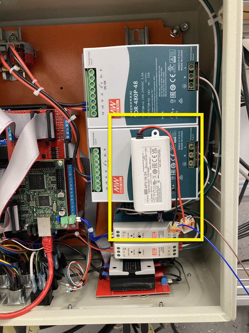
- Clean the surface of the 48V PSU where the new power supply will mount.
- Mount the APV to the PSU as shown. Apply pressure to ensure the adhesive makes full contact.
2.2.2
Revision Note
For CRP800-00E controllers older than 20.1.
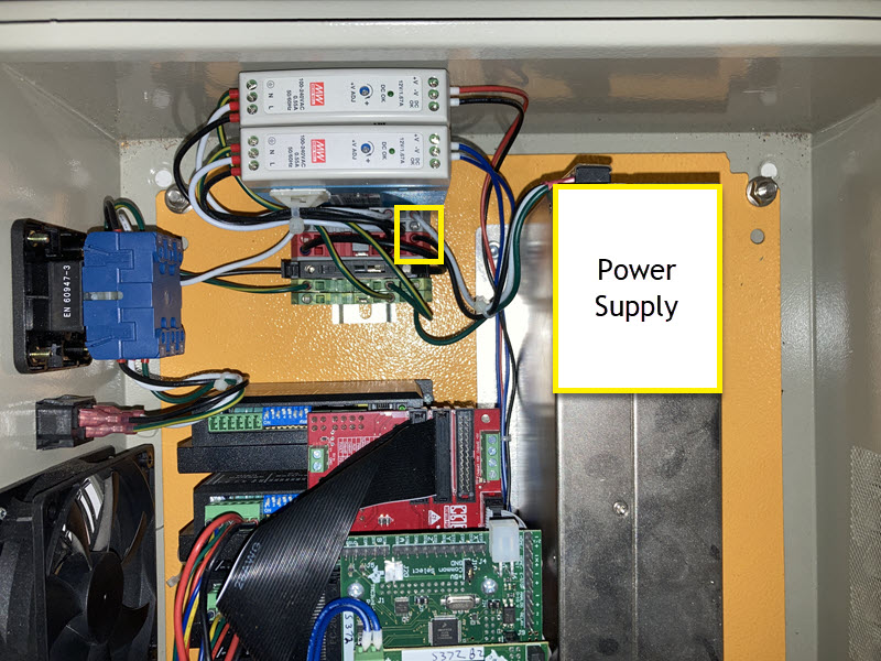
- Clean the surface of the 48V PSU where the new power supply will mount.
- Mount the APV to the PSU as shown. Apply pressure to ensure the adhesive makes full contact.
2.3 - Install the M12 connector
2.3.1
- Remove nut from the M12 connector.
- Put a shim washer on the inside and outside of the empty Motor Disable Switch hole.
2.3.2
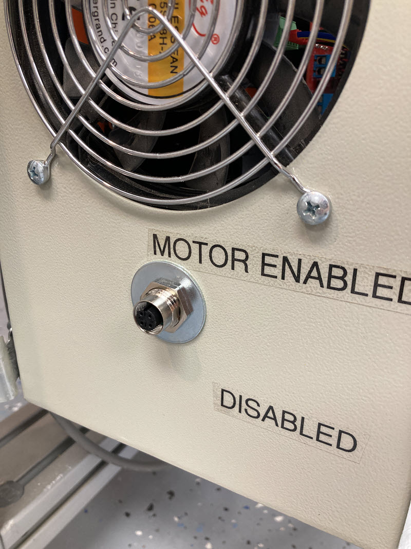
- Put the M12 connector through the shims and tighten the jam nut to pinch the washers and secure the connector.
3 - Finish Installation
- Connect the Brake cable to this new connector.
The brake will now disengage whenever the PSU is supplying power to the Z axis stepper motor.